• Skip to primary navigation
  • Skip to main content
  • Skip to primary sidebar
  • Skip to footer

Motion Control Tips

Automation • Motion Control • Power Transmission

  • News
    • Industry News
    • Editor Blogs
    • Video
  • Controls
    • HMIs
    • PC-Based Controllers
    • PLCs + PACs
    • Stand-Alone Controllers
    • Software
  • Drives
    • Servo Drives
    • Stepper Drives
  • Encoders
    • Absolute Encoders
    • Incremental Encoders
    • Rotary Encoders
  • Mechanical
    • Bearings
    • Brakes + Clutches
    • Belt + chain
    • Couplings
    • Gears + Gearing
    • Lubrication
    • Shock + Vibration Mitigation
    • Springs + Rings + Seals
  • Linear
    • Actuators
    • Linear Motors
    • Linear Encoders
  • Motors
    • AC Motors
    • DC Motors
    • Brushless Motors
    • Gearmotors
    • Piezo Motors
    • Servo Motors
    • Stepper Motors
  • Systems
    • Conveyors + linear transport systems
    • Gantries + Stages
    • Rotary Tables
    • Grippers + End Effectors
    • Robotics
  • Networks
    • Connections + Sliprings
    • Fieldbuses
    • I/O
    • Sensors + Vision
  • FAQs
    • Motion Casebook
    • Motion Selection Guides
  • Suppliers
You are here: Home / FAQs + basics / How do gearmotors impact reflected mass inertia from the load?

How do gearmotors impact reflected mass inertia from the load?

January 10, 2019 By Miles Budimir Leave a Comment

In any drive system (that is, a motor driving a load), there is going to be inertia. Specifically, the motor will have inertia as will the load. For a direct drive system (a direct motor-to-load connection) the individual inertias can just be added together in a straightforward way. However, for any other type of setup involving some additional mechanical drive components such as couplings or gears, the relationship changes.

gearmotors
Pictorial representation of a drive system with gears. (Image via Omron Industrial Automation)

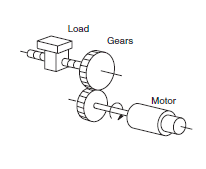
Specifically, when looking at how gears impact a drive system’s inertia, there are some basic ways to look at it. The basics; any gear will reduce the load inertia reflected to the motor by a factor of the square of the gear ratio. When looking at a gearmotor, this is basically just a motor with an embedded gearset in it, so the calculations and formulas for calculating inertia are the same.

In high performance motion control applications, it’s ideal for the reflected load inertia to equal the motor inertia. If inertia matching is the only concern, then the gear ratio can be calculated as:

N = √ (JLoad/ J Motor)

where N is the gear ratio, JLoad is the inertia of the driven load, and JMotor is the inertia of the motor.

Note: Another way to calculate gear ratio is by reference to the individual gears. For instance, if NIn is the number of gear teeth on the input gear and NOut is the number of gear teeth on the output gear, the gear ratio is then:

N = NOut / NIn

As for reflected inertia itself, this is best understood as the inertia of the load that is translated back to the motor through various drive components, in this case the gearing of the gearmotor.

So in a simple direct-drive system, the total inertia would be calculated like this:

JTotal = JLoad + JMotor

However, for a geared drive system such as a gearmotor, the total inertia is calculated using the equation:

JTotal = ( JLoad / N2 ) + JMotor

This is because, as stated earlier, the reflected load inertia is equal to the load inertia divided by the square of the gear ratio.

Update: Click here to read an update to this article with a few important corrections. 


You may also like:

  • gearmotors
    Hygienic, stainless gearmotor designs improve fish-processing plant
  • gear reducer
    How to select the best type of gear reducer
  • gearmotors
    How to design gearmotors for extreme ambient conditions
  • moments of inertia
    Moments of inertia: Definitions and equations
  • gearbox selection
    Three gearbox selection tools available online

Filed Under: FAQs + basics, Gearmotors

Reader Interactions

Leave a Reply

You must be logged in to post a comment.

Primary Sidebar

POWER TRANSMISSION REFERENCE GUIDE

DESIGN GUIDE LIBRARY

“motion
Subscribe Today

RSS Featured White Papers

  • Specifying electric rodless actuators: Ten tips for maximizing actuator life and system performance
  • The truth about actuator life: Screw drive survival
  • Top Ten Tips: How to specify electric rod-style actuators for optimal performance, reliability and efficiency

Footer

Motion Control Tips

DESIGN WORLD NETWORK

Design World Online
The Robot Report
Coupling Tips
Linear Motion Tips
Bearing Tips
Fastener Engineering.

MOTION CONTROL TIPS

Subscribe to our newsletter
Advertise with us
Contact us
About us
Follow us on TwitterAdd us on FacebookAdd us on LinkedInAdd us on YouTubeAdd us on Instagram

Copyright © 2022 · WTWH Media LLC and its licensors. All rights reserved.
The material on this site may not be reproduced, distributed, transmitted, cached or otherwise used, except with the prior written permission of WTWH Media.

Privacy Policy | RSS