
Piezo actuators operate on the inverse piezoelectric effect: when voltage is applied, the actuator contracts or expands. But when the actuator is blocked from moving (by a load applied in the direction of travel), it generates a force. This relationship between displacement and force in piezo materials is an inverse relationship. In other words, the more force an actuator must generate against a load, the less travel it can produce. A “free” actuator — one that experiences no resistance to movement — will produce its maximum displacement, often referred to as “free stroke,” and generate zero force.
Conversely, when an actuator is blocked from moving, it will produce its maximum force, which is referred to as the blocked, or blocking, force. Theoretically, when the actuator is blocked, it is working against a load with infinitely high stiffness. But materials with infinite stiffness don’t occur in the real world, so the blocking force is determined by applying a voltage to the actuator, with no load applied. This “free” operation, as described above, generates the actuator’s maximum displacement, or free stroke. A force is then applied to return the actuator to its original length. This force is measured and recorded as the blocking force.
The stiffness of the actuator is the ratio of blocking force to free stroke.
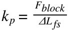
kp = stiffness of piezo actuator
Fblock = blocking force
ΔLfs = free stroke (nominal displacement) with no external load
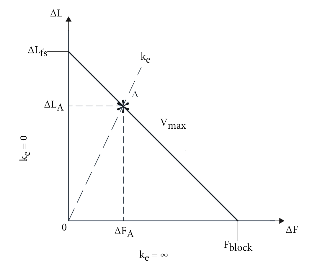
Image credit: APC International, Ltd.
There are two types of load that can be applied to a piezo actuator: a spring load, which increases as the actuator moves, or a constant load, which does not vary. The actuator’s ability to produce displacement and force depends on the type of load.
Piezo output force and displacement with a non-constant (spring) load
Many piezo applications, such as valve operation, introduce loads that vary with the piezo’s stroke — in other words, spring loads. When the stiffness of the applied spring load is low compared to the piezo stiffness, the piezo output force (Feff) is small. In other words, a spring (load) with low stiffness provides very little “blocking” for the piezo to work against in order to generate a force. Therefore, the piezo output force is greatly reduced from its maximum, or blocking, force.
![]()
Feff = force produced with spring load
ke = stiffness of applied load
On the other hand, the spring reduces the actuator’s displacement only slightly:
![]()
ΔL = displacement 0f actuator with spring load
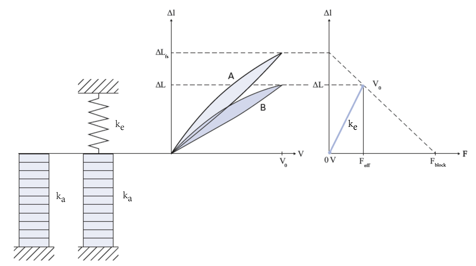
Image credit: PI Ceramic GmbH
A low-stiffness spring load — typically no more than 10 percent of the piezo stiffness — is generally recommended for preloading a piezo actuator to ensure the displacement is not severely reduced.
Piezo output force and displacement with constant load
When a constant load is applied, there is an initial deflection, or compression, of the actuator due to the load. This means the zero point of the working curve is offset, or shifted, but the actuator’s stroke is unaffected.
![]()
ΔLN = offset of the zero point with constant load
F = applied load
Some force is generated when the load is applied, causing the initial deflection, but once the actuator responds to the application of the load, its remaining work goes into generating the displacement. The zero point of the blocking force (maximum force) is also shifted, but is magnitude is not affected.
Image credit: PI Ceramic GmbH
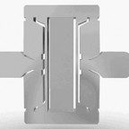
Feature image credit: Noliac


Leave a Reply
You must be logged in to post a comment.