Motion Control Tips

Automation • Motion Control • Power Transmission

  • News
    • Industry News
    • Editor Blogs
    • Video
  • Controls
    • HMIs
    • PC-Based Controllers
    • PLCs + PACs
    • Stand-Alone Controllers
    • Software
  • Drives
    • Servo Drives
    • Stepper Drives
  • Encoders
    • Absolute Encoders
    • Incremental Encoders
    • Rotary Encoders
  • Mechanical
    • Bearings
    • Brakes + Clutches
    • Belt + chain
    • Couplings
    • Gears + Gearing
    • Lubrication
    • Shock + Vibration Mitigation
    • Springs + Rings + Seals
  • Linear
    • Actuators
    • Linear Motors
    • Linear Encoders
  • Motors
    • AC Motors
    • DC Motors
    • Brushless Motors
    • Gearmotors
    • Piezo Motors
    • Servo Motors
    • Stepper Motors
  • Systems
    • Conveyors
    • Gantries + Stages
    • Rotary Tables
    • Grippers + End Effectors
    • Robotics
  • Networks
    • Connections + Sliprings
    • Fieldbuses
    • I/O
    • Sensors + Vision
  • FAQs
    • Motion Casebook
    • Motion Selection Guides
  • Suppliers
You are here: Home / FAQs + basics / How to address leakage current from motor to ground?

How to address leakage current from motor to ground?

September 14, 2018 By Miles Budimir Leave a Comment

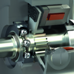
All electric motors operate with inherent losses from a number of different areas. Some are inherently mechanical (think friction losses as heat) while others are electrical, from current in conductors, also known as I2R losses, to losses due to hysteresis and eddy currents in the iron components of a motor.

One type of loss that is especially pernicious is leakage current from the motor to ground. The fact is that some small amount of current can flow from the motor to ground in all electrical equipment, usually as a result of some type of fault in the equipment or cabling. The amount for the most part is small, perhaps on the order of milliamps, but it is present nonetheless and poses a safety risk to human operators.

Several sources of leakage current are shown here including from the motor itself as well as from the motor cable. (Image via TDK)

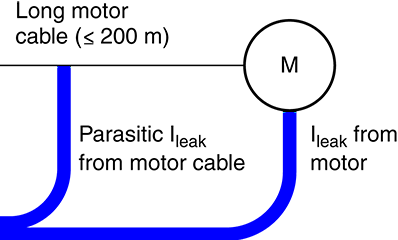
Leakage currents can flow through the insulation surrounding conductors. Electrically speaking, insulators have both resistance and capacitance, and leakage current can flow through both. Old or damaged insulation means a lower resistance and hence more potential current flow. Also, the longer the conductor the more capacitance, and therefore more leakage current flow. Typical allowable leakage currents in IT and medical equipment, for instance, are in the range of a milliamp or two to sub-milliamps.

So what is likely to cause leakage currents? For one, unshielded cables. Also, any other sources of electrical noise that can couple to the motor or motor cabling. Remember, leakage current can be an indicator of trouble in conductors and insulators. A common way to check for leakage current is to use a clamp-type current meter that fits around a conductor and gives a read-out of the current. The best ways to prevent leakage current are to always use shielded cables on motor installations and to make sure that these cables are grounded at both ends. Also, check cables and insulation for damage and replace ones that are broken or damaged.


You may also like:

  • motion components for cleanroom
    How to specify motion components for cleanroom environments: Part 2
  • servocontrols
    What are some different options for integrated servocontrols?
  • slip rings
    What are slip rings and why do some motors use…

  • For a given motion profile, when are other options for stopping…
  • wound field motors
    What are wound field motors and where are they applied?

Filed Under: FAQs + basics

Leave a Reply Cancel reply

You must be logged in to post a comment.

Motion Control Design Guide

RSS Linear Motion Tips

  • How does closed-loop stepper control work? (And why not just use a servo?)
  • One-piece ETX linear bearing/pillow blocks suitable for use in radioactive environments
  • What is Abbé error and how does it affect linear systems?
  • Follow these four tips when using L10 life to size linear bearings
  • New piezo driver with 1,200 W of power for fast switching applications
Subscribe Today

RSS Featured White Papers

  • What are dual-motion hybrid actuators and where do they excel?
  • Noise and vibration in leadscrew-driven motion designs and how to avoid them
  • Helical Planetary Gearboxes: Understanding The Tradeoffs
Tweets from https://twitter.com/Motion_Control/lists/motion-control-tweets
Motion Control Tips

DESIGN WORLD NETWORK

Design World Online
The Robot Report
Coupling Tips
Linear Motion Tips
Bearing Tips

MOTION CONTROL TIPS

Subscribe to our newsletter
Advertise with us
Contact us
Follow us on Twitter@motion_control
Add us on FacebookDesign World Network
Add us on LinkedInLinkedIn
Add us on YouTubeYouTube
Add us on InstagramInstagram

Copyright © 2019 · WTWH Media LLC and its licensors. All rights reserved.
The material on this site may not be reproduced, distributed, transmitted, cached or otherwise used, except with the prior written permission of WTWH Media.

Privacy Policy | RSS