Brushed DC motors are generally available in two types, depending on the construction of the stator: permanent magnet or wound field. Both motor types use current and windings to produce a magnetic field in the rotor, but they differ in how the stator magnetic field is produced: via permanent magnets inside the stator or with electromagnetic windings.
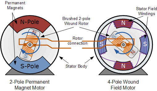
Wound field motors are further categorized by how the armature (rotor) and field (stator) windings are connected: series wound, shunt wound, or compound wound. Although performance characteristics vary among the three wound field motor designs, these motors generally have higher torque and speed capabilities than permanent magnet types.
Series wound DC motors
When the armature windings and field windings are connected in series, the motor is referred to as a “series wound” DC motor. Being connected in series means the current through the armature and the field windings is equal (Itotal= Ia= If), which allows the motor to draw a significant amount of current. And for series wound motors, torque is proportional to the square of current, so these motors are able to produce very high torque, especially at startup.
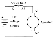
Image credit: National Instruments
On the other hand, series wound motors are not good for speed control. Here’s why: As the motor is loaded, its speed decreases, which causes the back EMF to decrease and net voltage to increase. This increased voltage causes armature current and field current to increase. But the current eventually becomes high enough to cause saturation of the magnetic field, and the flux between the armature and the stator will increase at a slower rate than the rate of current increase. Thus, the motor isn’t able to produce enough torque to bring the speed back to its pre-loaded value.
Voltage equation for DC motor:
Enet = E – Eb
Enet = net voltage
E = supply voltage
Eb = back EMF voltage
Based on these characteristics — high starting torque but poor speed control — series wound DC motors are often used as starter motors for large equipment with high inertia loads, such as cranes and elevators. They’re also found in consumer products that require only coarse speed control, such as blenders and hand tools.
The universal motor is a special design of the series wound motor that can operate on either DC or AC power.
Shunt wound DC motors
When the armature and field windings are connected in parallel, the motor is referred to as a “shunt wound” DC motor. (In electrical parlance, a parallel circuit is referred to as a shunt.) The parallel connection between the windings means the current supplied to the motor is divided between the armature and the field (Itotal= Ia+ If). The shunt (field) windings have a high resistance, preventing them from drawing high current at startup. But unlike series motors, shunt motors provide very good speed regulation.
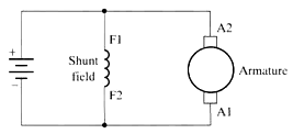
Image credit: National Instruments
The initial effect of an increased load on a shunt motor is the same as for a series wound motor: speed decreases, reducing back EMF and increasing net voltage. But in a shunt wound motor, the increased net voltage causes the armature current to increase. In a shunt motor, torque is proportional to armature current, so torque increases. This additional torque increases the motor speed to compensate for decrease that occurred when the load was applied. All of this happens instantaneously, making DC shunt motors essentially constant speed devices, regardless of load.
With low starting torque and constant speed, shunt wound DC motors are used in applications where good speed regulation is needed with varying loads, such as grinding machines and lathes. Another common use for shunt wound motors are processes that require constant tension, such as printing and winding.
Compound wound DC motors
A hybrid between the series wound and shunt wound designs, a compound wound DC motor has a field winding that is connected in series with the armature winding and another field winding connected in parallel (shunt) with the armature winding. There are several sub-types of compound wound DC motors, depending on whether the shunt field winding is connected only across the armature winding (referred to as a “short shunt” design), or whether the shunt field winding is connected across the series combination of the armature and the field winding (referred to as a “long shunt” design).
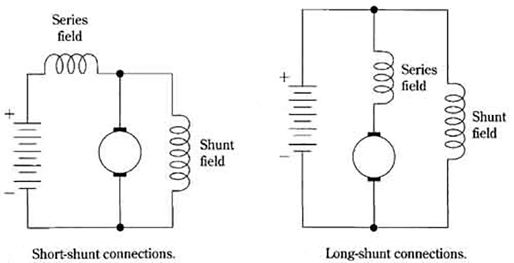
In the short shunt design, if the polarity of the shunt field matches the polarity of the series field and the armature, it is referred to as a cumulative compound motor and has the combined characteristics of series wound and shunt wound motors: high starting torque and good speed regulation. Conversely, if the polarity of the shunt field is opposite that of the series field and armature, it is referred to as a differential compound motor.
Cumulative compound motors are used in a wide variety of applications, from conveyors to heavy equipment such as ball mills. Differential compound wound motors have few practical applications, since they tend to overspeed when the load is reduced and to drop speed significantly when the load is increased.




Leave a Reply
You must be logged in to post a comment.