
Lenz’s law and back EMF work hand-in-hand. In electric motor operation, as the armature rotates inside the magnetic field, a voltage is produced. This voltage is commonly referred to as back EMF (electromotive force), since it acts against the voltage driving the motor.
Laws of electromagnetism
One of the fundamental laws governing electric motor operation is Faraday’s Law, which states that any change in the magnetic environment of a coil of wire will cause a voltage (EMF) to be “induced” in the coil. Regardless of how the change is produced—whether by moving the magnet and coil relative to each other or by changing the magnetic field—a voltage will be generated. The equation for this induced EMF is:
 Working hand-in-hand with Faraday’s Law is Lenz’s Law, which states that the polarity of the induced EMF is such that it produces a current whose magnetic field opposes the change which produces it. The induced magnetic field inside any loop of wire always acts to keep the magnetic flux in the loop constant. Simply stated, according to Lenz’s Law, the induced voltage (EMF) will oppose the driving voltage. Hence, the negative sign in the equation.
Lenz’s Law applied to motor circuits
Examining a simple motor circuit and considering the conservation of energy, we see that the net voltage across the motor will always equal the supply voltage plus the back EMF:
Net voltage = supply voltage + back EMF
Shown graphically:

Back EMF = -45 V
Net voltage across the motor = 150 V
Supply voltage = 195 V.
Back EMF = -45 V.
Net voltage across the motor, calculated according to Ohm’s Law (V = I x R = 10 A x 15 Ω), = 150 V.
This is in agreement with the equation for net voltage:
150 V = 195 V + -45 V
Back EMF in practice
Now let’s look at what happens when a load is applied to a motor.
First, the increased load causes the motor speed to decrease. Back EMF is directly related to speed, so when the speed decreases, so does the induced back EMF. From the equation above, we can see that if there is less back EMF, the voltage (and, therefore, current) across the motor will increase. This additional current produces the extra torque that the motor needs in order to regain its speed with the increased load.
In motor design, back EMF is influenced by the number of turns in the stator windings and by the magnetic field. Motors are designed with a back EMF constant that allows the motor to draw the rated current and deliver the rated torque when running at the rated speed.
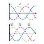
Back EMF can have either a sinusoidal (AC) or a trapezoidal (DC) waveform. The shape of the back EMF is important, as it determines the type of drive current and commutation method that should be used for the motor.
Circuit diagram and example taken from New South Wales, Department of Education and Training, 2007.

Leave a Reply
You must be logged in to post a comment.