 Although wave-spring applications abound, there are basic rules to define spring requirements and determine whether a design can use a stock or standard spring or needs a special wave spring.
The first and most important consideration is the load the application will apply to the wave spring. Required load is defined as the amount of axial force the spring must produce when installed at its work height.
Read the related article: What are Wave Springs for Motion Designs?
Some applications require multiple working heights, so that there are critical loads at two or more operating heights. Often minimum and maximum loads are satisfactory solutions, particularly where tolerance stack-ups are inherent in the application.
In any case, remember to consider whether the spring will be subject to high temperature, dynamic loading (fatigue), corrosive media or other unusual operating conditions. Solutions to various environmental conditions typically call for special materials that withstand operating stresses.
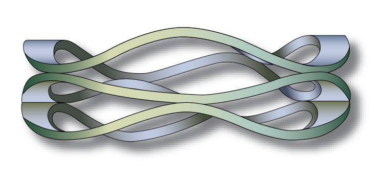
Wave springs install into working cavities. These usually consist of a bore (in which the spring operates) or a shaft that the spring clears. The spring stays positioned by piloting in the bore or on the shaft. The distance between the loading surfaces defines the axial working cavity or the spring’s work height. This is where the spring’s material cross-section is important to the overall design.
Four critical factors dictate the most suitable wave spring for a given application: Physical design constraints (including bore geometry, shaft, ID, OD and so on), the application load, the working height at which the design applies load, and the spring material that will best withstand the application environment. (More after the jump.)
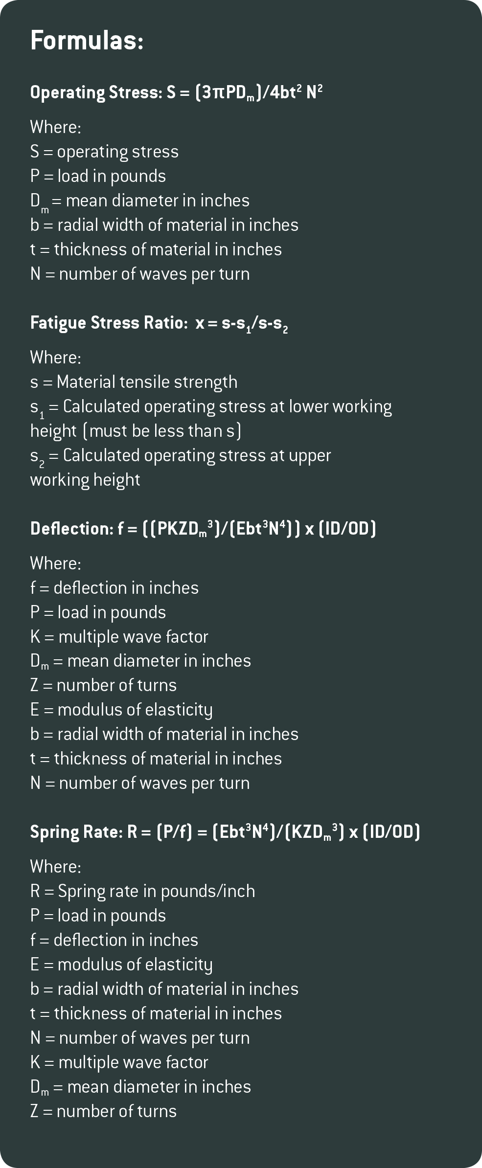
If a spring is designed for a static application, make sure that the percent stress at working height is less than 100%. Springs will take a “set” or length loss in operation due to the high stress condition of the spring if subjected to a higher stress. If a spring is designed for a dynamic application, make sure that the percent stress at working height is less than 80%. Springs will take a set if put under higher stress. If the work height per turn is less than twice the wire thickness, the spring operates in a non-linear range and actual loads may exceed calculated loads.
• Number of turns must be between 2 and 20
• Number of waves per turn (N) must be in half-turn increments
• Minimum radial wall = (3 times the wire thickness)
• Maximum radial wall = (10 times the wire thickness)
One caveat: It’s best to avoid situations that compress a wave spring to solid. In addition, account for the expansion of the OD as well as the OD tolerance when designing a spring to fit in a bore or over a shaft.
Leave a Reply
You must be logged in to post a comment.