All electric motors experience rotational losses during the conversion of electrical power to mechanical power. These losses are generally categorized as magnetic losses, mechanical losses, copper losses, brush losses, or stray losses, depending on the underlying cause and mechanism. Included in the category of magnetic losses are two types — hysteresis loss and eddy current loss.
Hysteresis loss
Hysteresis loss is caused by the magnetization and demagnetization of the core as current flows in the forward and reverse directions. As the magnetizing force (current) increases, the magnetic flux increases. But when the magnetizing force (current) is decreased, the magnetic flux doesn’t decrease at the same rate, but less gradually. Therefore, when the magnetizing force reaches zero, the flux density still has a positive value. In order for the flux density to reach zero, the magnetizing force must be applied in the negative direction.
The relationship between the magnetizing force, H, and the flux density, B, is shown on a hysteresis curve, or loop. The area of the hysteresis loop shows the energy required to complete a full cycle of magnetizing and de-magnetizing, and the area of the loop represents the energy lost during this process.
Image credit: NDT Resource Center
The equation for hysteresis loss is given as:
Pb = η * Bmaxn * f * V
Pb = hysteresis loss (W)
η = Steinmetz hysteresis coefficient, depending on material (J/m3)
Bmax = maximum flux density (Wb/m2)
n = Steinmetz exponent, ranges from 1.5 to 2.5, depending on material
f = frequency of magnetic reversals per second (Hz)
V = volume of magnetic material (m3)
Eddy current losses
Eddy current losses are the result of Farady’s law, which states that, “Any change in the environment of a coil of wire will cause a voltage to be induced in the coil, regardless of how the magnetic change is produced.” Thus, when a motor core is rotated in a magnetic field, a voltage, or EMF, is induced in the coils. This induced EMF causes circulating currents to flow, referred to as eddy currents. The power loss caused by these currents is known as eddy current loss.
Motors armature cores use many, thin pieces of iron (referred to as “laminations”), rather than a single piece, because the resistance of individual pieces is higher than the resistance of one, solid piece. This higher resistance (due to smaller area per piece) reduces eddy currents, and in turn, eddy current losses. The laminations are insulated from each other with a lacquer coating to prevent the eddy currents from “jumping” from one lamination to another.
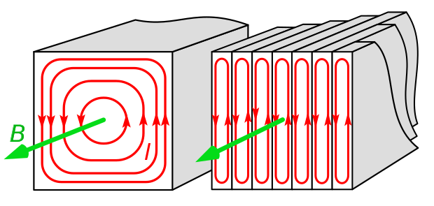
Image credit: wikipedia.org
The equation for eddy current loss is given as:
Pe = Ke * Bmax2 * f2 * t2 * V
Pe = eddy current loss (W)
Ke = eddy current constant
B = flux density (Wb/m2)
f = frequency of magnetic reversals per second (Hz)
t = material thickness (m)
V = volume (m3)
Magnetic losses are so named because they depend on the magnetic paths in the motor, but they are also referred to as “core losses” and “iron losses.”
Leave a Reply
You must be logged in to post a comment.