Integrated automation and motion control simulation software provides simple and quick virtual commissioning for machine builders.
By Kevin Wu and Colm Gavin | Siemens Digital Industries
In the development of any new machine or plant, faults are almost inevitable. Failure during commissioning is especially problematic, because it’s likely to significantly increase costs and delay the designs schedule. What’s worse, failure of physical machine components can cause harm to equipment or even human operators.
So to mitigate these risks and improve design efforts, original equipment manufacturers (OEMs) are turning to digital twins and virtual commissioning. These software-based design techniques empower OEMs to identify flaws and inefficiencies in designs prior to working with real components and assembly.
Virtual commissioning involves modeling and simulating a machine’s operation … typically prior to physically building anything. Such commissioning helps refine functionality during earlier stages of development, when alteration costs and consequences are much more modest than those made at later design stages.
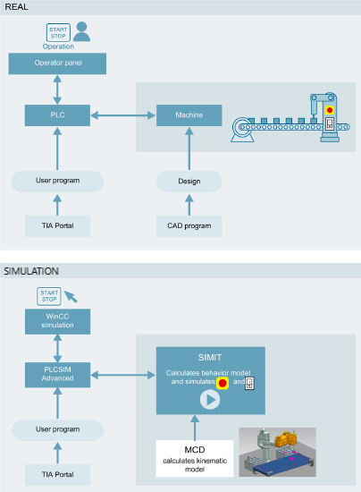
A machine’s digital twin consists of three parts:
• The automation model
• The electrical and behavior model
• The physical or kinematic model.
Ideally, all are concurrently considered for the most accurate representation of the machine. That said, not all applications require all three models.
The physical or kinematic models are primarily needed for early verification of machine concepts because they provide visualization of the machine in a 3D model and predict interferences — and verify how product will move through the machine. But for automation engineers, it may be sufficient to use just the automation and electrical models.
In this article, we detail virtual commissioning using just the automation and electrical models. Deploying these two parts of the digital twin lets manufacturers of small to medium-sized machines gain most of virtual commissioning’s substantial benefits.
Machine-automation commissioning virtualized
Virtual commissioning is beneficial for machine builders because it minimizes guesswork when spinning up a machine for the first time … and it provides a way to tackle challenges prior to physical commissioning. No wonder it’s become increasingly common as machine mechanics have become more sophisticated.
Virtual commissioning is essential to today’s machine-development lifecycles because it lets programmers visualize and test complex moves that are otherwise difficult to plan.
A digital twin — a digitized replica of a machine or other automated device — is the typical benchmark for modeling and simulation. As mentioned, it consists of three models:
- The automation model, made up of a PLC program and visualization.
- The electrical and behavior model, made up of active components — such as motor drives, actuators, and sensors — along with the behavior of peripheral components, such as motors and valves.
- The physical or kinematic model consisting of mechanical components.
Automation models link graphical visualization with the machine’s PLC code that in turn executes “under the hood” in the virtual model. In this way, automation models give programmers a way to use pre-validated blocks of prewritten software code (representing a move or mechanical machine component) in their code for motion control. Ultimately that reduces upfront testing requirements.
The best pre-validated software blocks provide user-friendly step-by-step setup guides via a graphical user interface (GUI) and represent moves or mechanical components on the machine. There are data blocks associated with this prewritten code, and these are easily accessible in the PLC programming environment. That permits simple viewing of the motion-control part of an automation program.
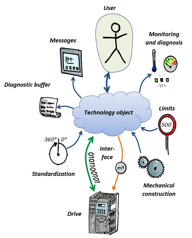
Typically, an automation model includes pre-validated software blocks for controlling speed, position, synchronous axes, and cams. What’s more, these software blocks can be used for processing data from external encoders and sensors. A common device such as a motor drive is assigned to one software block … and the latter includes all configuration and status data.
Users can include prewritten software blocks and their associated motion-programming blocks from a prebuilt library — and then reuse them within a project. All prewritten blocks can be shared among projects, with a project’s configured motor drives reassigned to the reused blocks.
The second part of a digital twin — electrical systems
The electrical and behavior model of a machine’s digital twin can simulate the real-world performance of active components and their peripherals in response to the automation system programming, and the environmental conditions — such as temperature and pressure. Advanced software provides the flexibility to run electrical and behavior simulation using either a physical or a virtual controller.
As with the automation model, programmers can pull from a library of standard components for creating electrical and behavior models of drives, actuators, motors, valves, and other devices. This improves the initial accuracy of models while avoiding the need for programming simulations from scratch.
Because the electrical and behavior model functions in concert with the automation model, engineers can test automation code by varying ambient conditions — simulating failure conditions to validate PLC program response and performing other actions.
The third part of a digital twin — kinematics
Digital twins can also include physical and kinematic models. Created using CAD data, such models characterize mechanical properties in virtualized space to enable visualization of machine behavior.
Connectivity between a digital twin’s three models facilitates identification of machine errors and bugs before any physical or working prototyping.
Accessible virtual commissioning
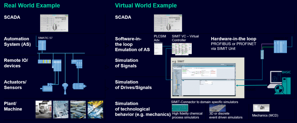
For applications consisting mainly of PLCs and motor drives, basic motion-control simulation software (with automation software) lets machine builders reap most of the benefits of using digital twins during their design work. Automatic generation of virtual models is directly from the prewritten software blocks in the automation program, creating automation and electrical and behavior models for simulation.
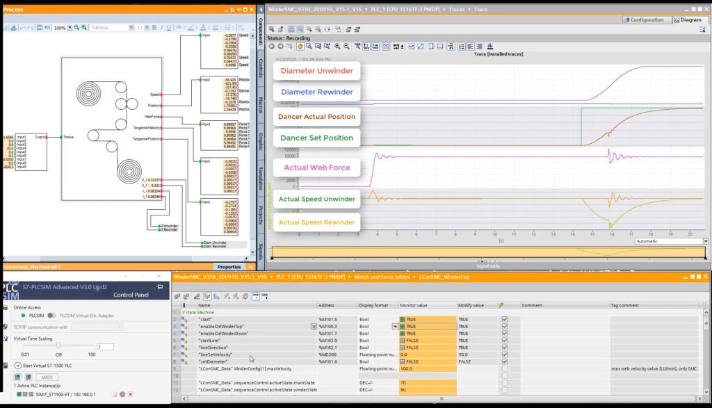
Using software or hardware-in-the-loop, developers can visualize the interplay among automation controllers, and signals to and from periphery objects, such as drives.
Configuring such simulation requires minimal effort for developers because the baseline models are generated as standardized functional mockup units or FMUs. Each FMU is continuously updated by the manufacturer as they issue software and firmware updates to the corresponding physical device … ensuring accurate behavior of the simulation and consistent model-based development. Like prewritten software blocks from suppliers, FMUs are pre-validated to physical components — reducing the time needed to configure simulations while providing more opportunity to optimize machine efficiency.
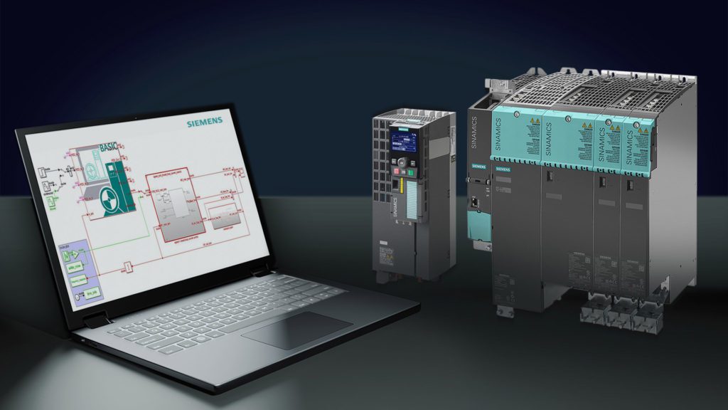
Consider a PLC and drive model coupling application scenario where integrated automation and motion control simulation software adds value to development:
- Calculated load profiles are loaded into an integrated selection or sizer tool, and the user can choose from a list of drives fitting the application requirements.
- The necessary drive parameters and the known interfaces are available for simulation.
- The user must only configure the portion of the drive needed for simulation purposes. A time-consuming, complete virtual commissioning of the drive isn’t required … saving time and money.
- The drive simulation model is pre-validated against the real drive using the same test vectors.
Using simulation as a tool for development and production also improves communication among teams and accelerates verification, especially when workers are remote. This enables more agile software development, because modifications for operational improvement become apparent long before real motors are spinning.
Two examples of simulation software in use
A global leader in heat transfer and fluid handling recently integrated one motion control simulation software package into its standard workflows to facilitate virtual testing. Observing and updating drive control models throughout development lets the company identify errors early for fault-free integration during real commissioning. The software has also enhanced the company engineers’ capability to test from anywhere, because they no longer need a physical drive and motor to tweak and optimize motion sequences. Nor do they waste time physically connecting test components and sensors.
Recently a bearings manufacturer also used motion control simulation software to enhance its testing capabilities. A grinding machine was scheduled to go through a software upgrade and relocation but testing it in the new location would’ve cost an estimated 20 days of downtime — because the machine was in production use elsewhere. By creating a virtual model of the machine and performing a hardware-in-the-loop test at the new cell, the engineering team assembled a suitable configuration for the grinding machine with just four days of virtual debugging. When they connected the real machine to the new cell, no interface errors occurred … and production was ramped back up seamlessly.
Simulation enhances real commissioning and production
Virtual commissioning is an invaluable tool for machine builders … and for those looking to simulate prior to prototyping, motion control simulation software is an achievable entry point. Through automatic generation of automation and electrical and behavior models, it provides simple and accurate means for both hardware and software-in-the-loop testing.
This lets engineers optimize testing procedures and work more collaboratively. It also helps machine builders cut development costs because they can identify many errors virtually before working with real parts, and it reduces safety risks during actual commissioning, while promoting continuous and efficient operation.
Siemens | industry.siemens.com
 Kevin Wu is the SIMATIC motion controller product marketing manager for Siemens Industry in the United States. He has more than 15 years of experience with Siemens automation and drives, and technical engineering experience with production machines.
Kevin is a motion safety consultant for machine system design.
 Colm Gavin is the Portfolio Development Manager for Siemens Digital Industries Software and is responsible for the promotion of digitalization topics for machine and line builders in the United States. With over 20 years at Siemens, he is leveraging his experience in discrete manufacturing to help companies take advantage of new innovations coming with Industry 4.0. Prior to his current role, Colm was responsible for marketing Siemens’ Totally Integrated Automation Portal software in the U.S. and worked on the software’s development with Siemens Germany.
Leave a Reply
You must be logged in to post a comment.