Industrial power tools have operating profiles that differ from those of most other motor-driven applications. That’s why motors that go into these tools need specialized designs.
By Thomas Baile, Business Development Manager | Portescap
Power-tool speed stage: At first (as the tool drives a fastener to thread into place or the jaws of a cutting or gripping tool approach a workpiece) there’s little resistance.
Power-tool torque stage: Then when the tool performs the more forceful work of tightening, cutting or gripping, there’s a sudden torque demand.
These alternating speed and torque cycles constantly repeat in industrial power-tool applications even while necessitating different speeds and torques for various durations. That’s why such tools — especially those that are battery-operated so running off low voltage and limited available power — benefit from special motor designs that minimize losses.
As we’ll explore, motors that also operate at faster free-run speeds for the speed stage can trim cycle times to boost productivity … and motors that deliver high peak torque during the torque stage can perform a wider range of tough jobs without excessive heating.
Selecting and optimizing brushless motors for power tools
Consider the primary options for handheld industrial power tools — brushed dc motors and brushless dc motors. Battery-powered industrial power tools run on low voltages of 12 to 60 V … so here, brushed dc motors are typically economical but have limited life. The brushes exhibit modes of wear due to electrical influences (from current related to torque) and mechanical influences (due to the friction associated with speed).
Brushless dc motors are more reliable in power tools, as they’re less susceptible to mechanical wear (no brush friction) and can sustain high peak current (no brushes) during the tightening stage, providing far greater life in the hand tool. Brushless dc motors are better suited than brushed dc motors for industrial power tool applications because they require high speed and high peak current.
Brushless dc motors for power tools are typically one of two configurations:
Conventional inrunner motor configurations include permanent magnets on the rotor with three stator windings around the rotor.

Outrunner (external-rotor) configurations have it reversed — so coils are innermost on the stator and the magnets are on the O.D. In other words, the stator coils form the motor center while the permanent magnets on the rotor’s inner surface spin within an overhanging rotor surrounding that core.
Inrunner motor configurations excel in handheld industrial power tools because they have reduced inertia, lower weight, and lower losses. Their longer length and smaller diameter also complement handheld designs for ergonomics. Plus a lower rotor inertia brings better tightening and gripping control.
Brushless dc windings can be constructed in different physical configurations:
Motors with slotted stators: Here, the coils wind through the slots around the stator. Magnetic induction in the lamination is high because the airgap between the laminations (stator) and magnet is small. So, the motors allow a small magnet diameter. The volume of the copper is limited by the slot space and the difficulty of winding within the slot. Having the coil inside the stator slots is advantageous in that it reduces coil-stator assembly thermal resistance.
Without current, the rotor has preferred magnet positions in front of the lamination. That means the motor is prone to generating a cogging or detent torque. One way to decrease the detent torque is to skew the lamination.
But again, slotted motors are inherently robust because the coil is in the lamination.
Motor with slotless stators: Slotless motors have coils wound in a dedicated operation. This coil goes into the motor airgap during motor assembly. Magnetic induction in the coil is lower than in slotted motors because the airgap is larger. So the motor diameter is usually optimized for magnetic induction with a given copper volume.
In fact, induction in slotless motors is usually less than that of a slotted brushless motor. So bigger magnets are typically used to compensate for the loss of induction. One caveat to this solution is that it can increase rotor inertia.
But slotless motor power density is a strength. R/K² — the ability to maintain speed under load, with lower values being better — is low in slotless motors because induction for a given copper volume is optimized … as evidenced by a sloped curve. Without circulating current, the rotor sees a continuous permeance. That means slotless motors don’t exhibit cogging or detent torque. Iron losses at high speed in slotless motors are also far smaller than those of comparable designs.
There is another caveat: Slotted motors can handle higher temperatures than slotless motor designs — even to 200° C compared to 150° C, to give a typical comparison. That in turn allows more torque generation. Even so, in power tools usually the limiting factor is maximum temperature over time — to an average maximum of 47° C — or so — to accommodate what’s comfortable for the typical hand-tool user. Beyond that value, heating can become uncomfortable for the operator holding the tool. Safety regulations also require maximum temperature to be held lower.
| Slotted brushless dc motors | Slotless brushless dc motors (Ultra EC) |
|
| Pros | Small thermal resistance (coil/casing)
Maximum speed in excess of 100krpm Fully customized motors Hipot capability (to 2,500 V) Torque |
Smooth operation and no cogging
Little iron losses at high speed … low operating temperature and easier control Low noise and vibration Winding flexibility |
| Cons | Cogging
No standard products |
Autoclavable option not available
High thermal resistance |
Of course, the electrical performance of a motor is defined by the magnetic circuit. The magnet has a fixed value but the second component (the copper winding) can be easily modified. By changing with the wire diameter and number of turns, the motor’s torque constant kt and resistance R can be fine-tuned for torque and speed. Consider the modes of industrial power-tool operation:
During the speed stage, the motor must operate at high rpm with little resistance:
ω = (U – R · I ) / kt
Where ω = Speed in rad.sec-1 and U = Voltage; R = Resistance in ohms and I = Current in Amps; and kt = Torque constant in Nm/A. Because the torque constant is in the denominator of the calculation, smaller kt values make for higher RPMs. This allows more operations in the same time period which boosts productivity.
Now consider the power tool’s torque stage — when the motor must deliver peak torque at low speeds. Torque is the product of the torque constant and current:
C = kt · I
Where C = Torque in Nm and I = Current in Amps. Higher kt values here make for a higher output torque at a given current. So by adjusting a motor winding’s kt design engineers can optimize either the speed or the output torque to balance optimization of torque with that of speed operation to reduce overall working cycle time. There is no unique solution: kt has to be chosen as the best compromise for a range of working profiles. Motor design experts can support one in this coil design process based on simulations and experience.
Reviewing thermal losses of motors during operation
Consider the losses of a typical industrial power-tool operating cycle. There is a relationship between copper losses and torque. So the design engineer may opt for a motor with a low kt value to increase speed … and then compensate for a low kt with more current (I) to get target output torque. But higher current increases copper losses:
Copper losses = R · I2
So with higher current comes faster heating of the motor and power-tool — thus limiting maximum possible torque. That’s why power-tool motors should be designed to draw as low a current as possible … to limit heat dissipation (and keep tool temperature cool enough to handle) and conserve battery life.
Now consider iron losses and how they relate to speed. Eddy-current losses increase with the square of speed to heat the brushless motor even if it’s just rotating under a no-load condition. That’s why high-speed motors need special design features to limit eddy-current heating.
Increased power-tool speed promptly makes iron losses exceed copper losses. So motor windings should be tuned for each duty cycle to minimize losses. Ultra EC winding technology greatly reduces iron and copper losses — which in turn gives design engineers more flexibility.
More specifically, some new electronically commutated (EC) brushless motors on the market build on a slotless motor design with specialty coil technology. These reduce copper losses because unlike slotless motors with skewed windings, they have windings parallel to the motor axis to maximize magnetic force and power. Plus they reduce iron losses at high speed. Among other benefits, these motors optimize speed and torque for the most challenging applications — including power tools that take the form of fasteners, grippers, and cutting tools.
Two example applications for EC motors in power tools
Assume for one design we have an average duty cycle including two seconds of moderate free speed — as in a pruning shear, nutrunner, gripper, or stapler. Speed is 20,000 rpm and at 2 seconds torque demand goes to 0.84 Nm.
Assume for the other design we have a heavy-duty cycle including three seconds very fast free speed — as in an automotive nutrunner optimized for productivity. Here, speed is to 40,000 rpm and at 3 seconds torque demand goes to 0.69 Nm.
For the first design:
| Brushless motor type | Ultra 64 | Skewed winding | Slotted motor | Ultra 90 |
| Ø · L (mm) | 30 · 64 | 30 · 64 | 28.5 · 88.5 | 30 · 90 |
| Poles | 4 | 4 | 4 | 4 |
Here straight-coil EC Ultra motors are more efficient (exhibiting less losses) than skewed-winding or slotted motors.
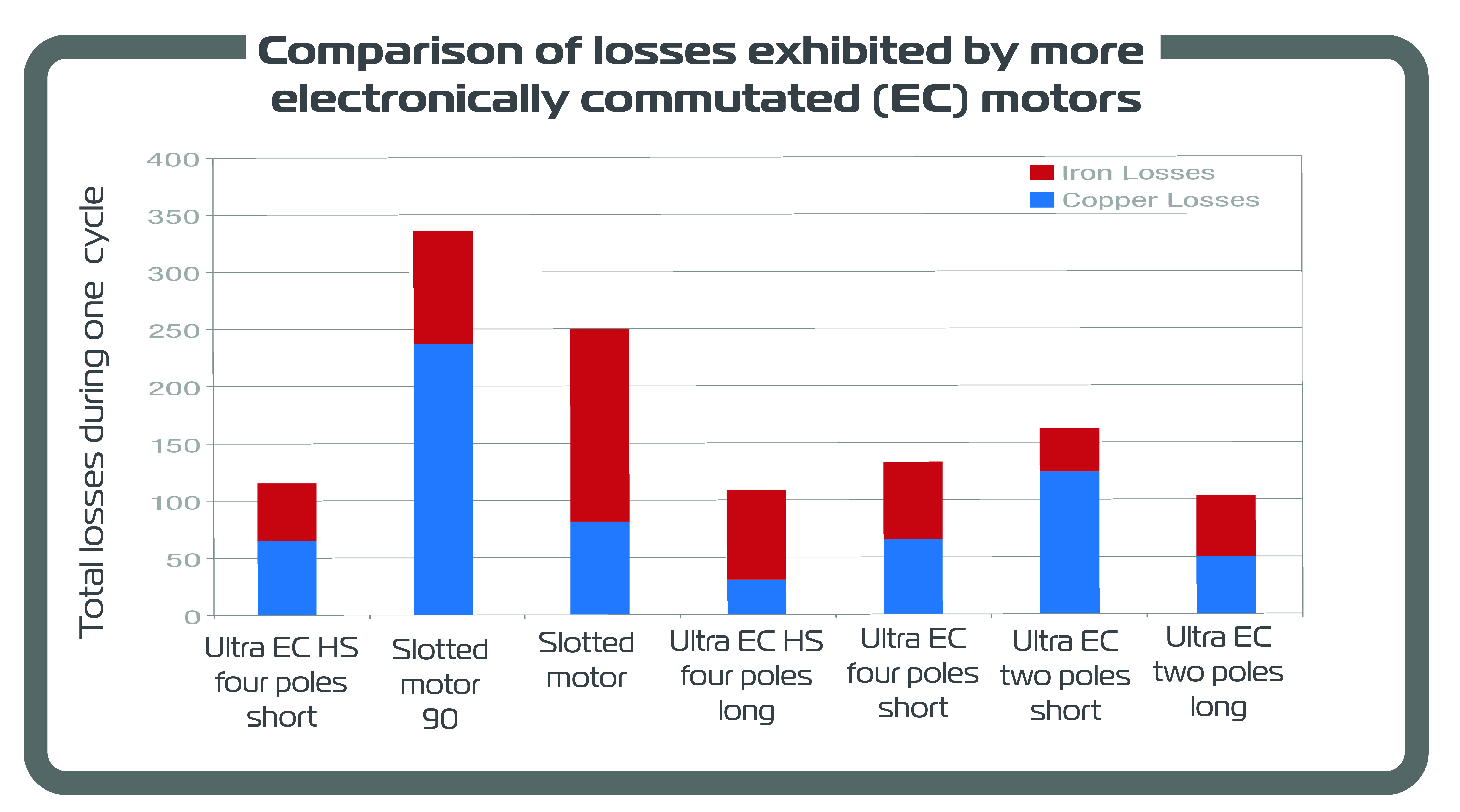
For the second design:
| Brushless motor type | Ultra 64 HS | Slotted 90 | Slotted 100 | Ultra 90 HS | Ultra 64 | Ultra Speed 60 | Ultra Speed 80 |
| Ø · L (mm) | 30 · 64 | 28.5 · 88.5 | 34 ·99 | 30 · 90 | 30 · 64 | 35 · 60 | 35 · 80 |
| Poles | 4 | 4 | 4 | 4 | 4 | 2 | 2 |
 There are higher iron losses than in the standard-duty design because the speed is doubled. Even so, straight-coil EC Ultra motors are still more efficient than skewed-winding or slotted motors.
Portescap | www.portescap.com
For more than 25 years, leading manufacturers have relied on Portescap’s products, expertise, and support to develop corded and battery-powered tools while improving quality control and flexibility. Portescap innovation has helped transitions from pneumatic to electric tools while raising industrial power-tool performance standards. In 2013, Portescap patented the first slotless motor design with its Ultra EC coil.
Leave a Reply
You must be logged in to post a comment.