
This piece comes to us from Charles E. Harris, Partner at Plymouth Machine Integration LLC.
False brinelling is a kind of damage from fretting — wavy, chipped, or corroded damage on metal contact surfaces of power-transmission devices subject to wearing from repeated surface motion. It’s a problem in assemblies with mechanical subsections that move slowly but are subject to high vibration, and it’s especially common in large bearings with rolling elements in rolling-element bearing applications — in wind turbines, for example.
First some basics:
Explanation of false versus true brinelling
False-brinelling damage leaves series of divots that resemble those of true brinelling, which is permanent indentation of a component’s hard surfaces. However, true brinell damage is permanent material deformation (without loss of material) and occurs during one load event. In contrast, false brinelling is material wear or removal that happens over time because of vibration and light loads.
More specifically, true brinelling, named after the Brinell hardness scale, leaves repetitive series of indents on the working surfaces of mechanical parts. Most common on hydraulic pistons and bearings, it happens when a material surface failure caused by Hertz contact stress that exceeds the material limit — as when a heavy load impacts a small surface area, for example. Ultimately, brinelling causes chattering, vibration, and other forms of wear.
In contrast, false brinelling happens when a bearing design only redistributes lubricant during large rotations of all bearing raceway surfaces. When such bearings only move a little bit, small oscillations or vibrations can squeeze lubricant out of loaded spaces. Then wear begins and only accelerates with move vibrations. What’s more, sometimes small bits of material break off the raceway and oxidize. This material further abrades the damaged surface and accelerates wear.
False brinelling on wind-turbine bearings
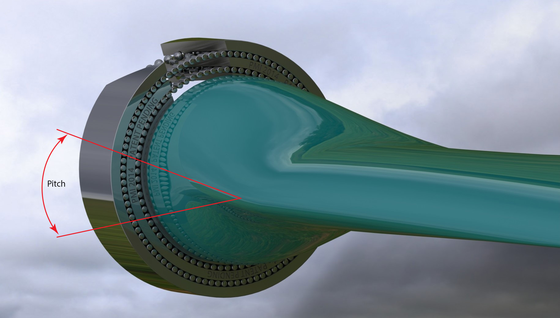
False brinelling often develops on wind-turbine parts where bearings in pitch-control mechanisms can remain in one set position for long periods of time. In such situations, the lubricant film is gradually displaced, allowing metal to metal contact. The vibration in the joint causes this contact to produce physical damage. Purposely inducing small amounts of relative motion can be helpful, but the benefit is limited since the lubricant can be pushed aside in either direction.
For example, consider the blade pitch control on a wind turbine. Here, blade pitch angle is set to match aerodynamic force with wind speed and load demand. Changes to the pitch are infrequent and small, leading to damage to the bearings supporting the blade. Intentional motion can be imposed on the system to promote lubricant flow. This motion is called dither. The minimum motion required is a function of the spacing of rolling elements within the bearing. Dither puts the blade off of the preferred angle, and therefore decreases the efficiency of the turbine. Minimizing the required dither helps to maximize overall system efficiency.
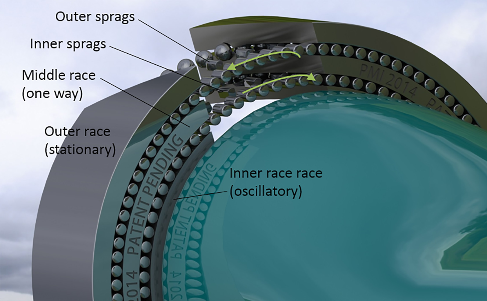
Plymouth Machine Integration has made a provisional patent application for a design that uses two concentric one-way bearings, installed such that their actions are opposed. With a modest amount of oscillatory motion, it induces large movements of the intermediate race — and both sets of rollers. That evenly distributes the lubricant.
How does it work? The motion in the intermediate race is from a one-way clutch in one of the two bearings holding that race motionless with respect to first the inner, then the outer race, depending on the direction of rotation within the period.
In this way, the design avoids false brinelling by maintaining a lubricant film and preventing adhesion of surface asperities.
One caveat: This design doesn’t resolve issues from assemblies that lie motionless for substantial periods of time between uses — on spare electric motors, for example. This needs oscillatory motion of a magnitude large enough to engage the one-way clutch … oscillatory motion that’s either natural to the operation of the machine or imposed on the controls.
For further information, visit plymouthmachineintegration.com.
Also download the classic resource, Tribological Challenges in Wind Turbine Technology.
About the source: Charles E. Harris has twenty years of experience in the design, testing, and development of powertrain components and systems. Seventeen of those years were at Ilmor Engineering, Inc., a high-level engineering company for motorsports and marine pleasure-craft powertrains. According to Harris, experience in these fields meant study to bearings operating under difficult conditions … both on engines, such as engine throttle shafts, and in test equipment, such as dynamometer trunnion bearings.
Leave a Reply
You must be logged in to post a comment.