
Updated May 2016 || Options for linear motion abound, but today’s rack-and-pinion sets are precision mechanical devices that in some cases deliver performance rivaling that of electromechanical alternatives.
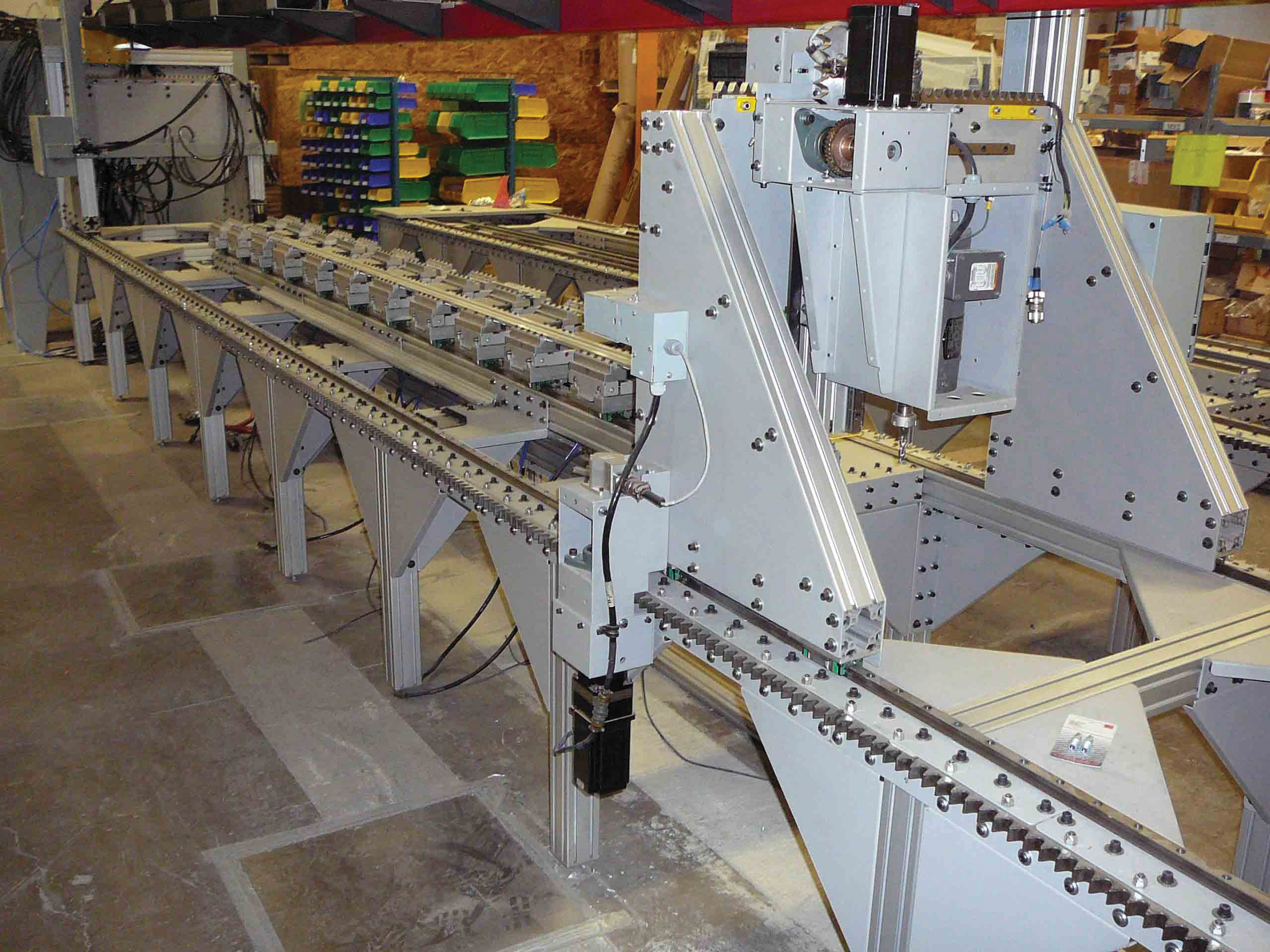
First modernized 150 years ago to drive railway trains up steep passages, rack-and-pinion sets today are useful in everything from small consumer devices that move a few ounces to large industrial machinery that moves tons of load. That includes off-highway machinery, food-processing, packaging lines and other applications that involve reciprocating motion.
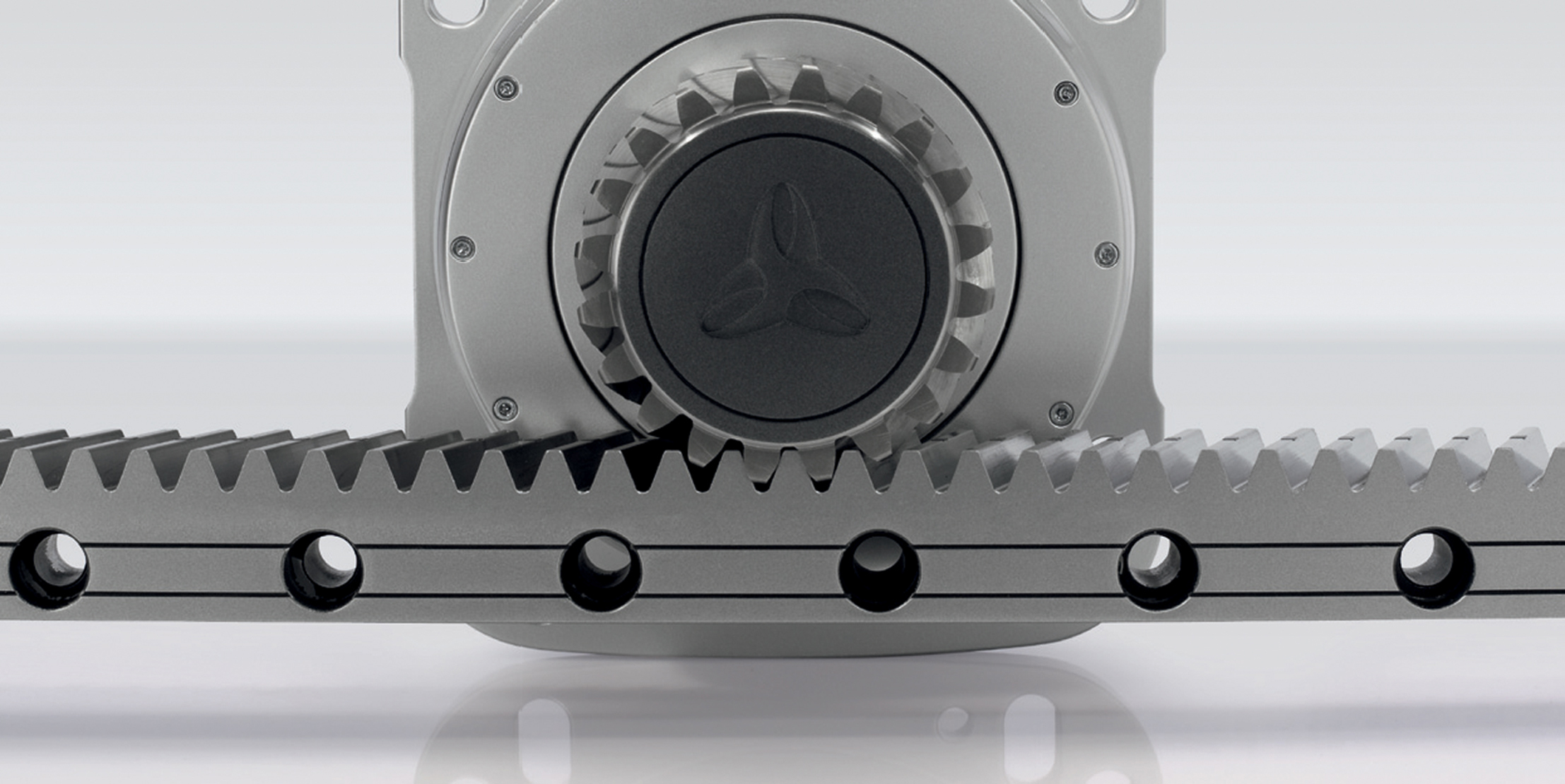
Here’s how rack and pinions work: A parallel-axis gearset converts rotary motion to linear motion through a motor-driven pinion (essentially a specialty spur gear or engineered roller) that engages the rack (which is essentially a gear of infinite diameter). In rare cases, an input moves the rack to get pinion rotation. Usually, rack-and-pinion sets get paired with servomotors or (less commonly) with step motors. (More after the image.)
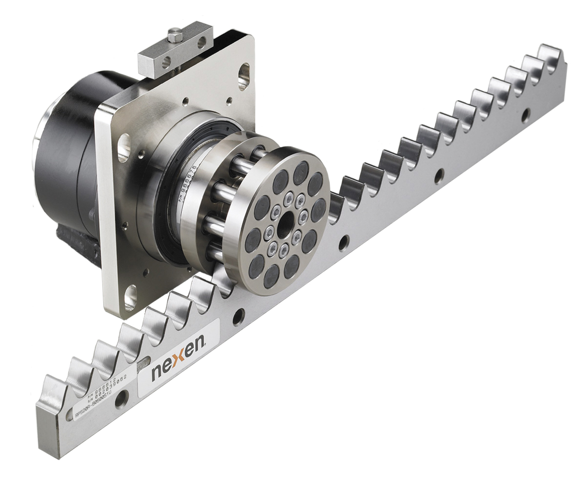
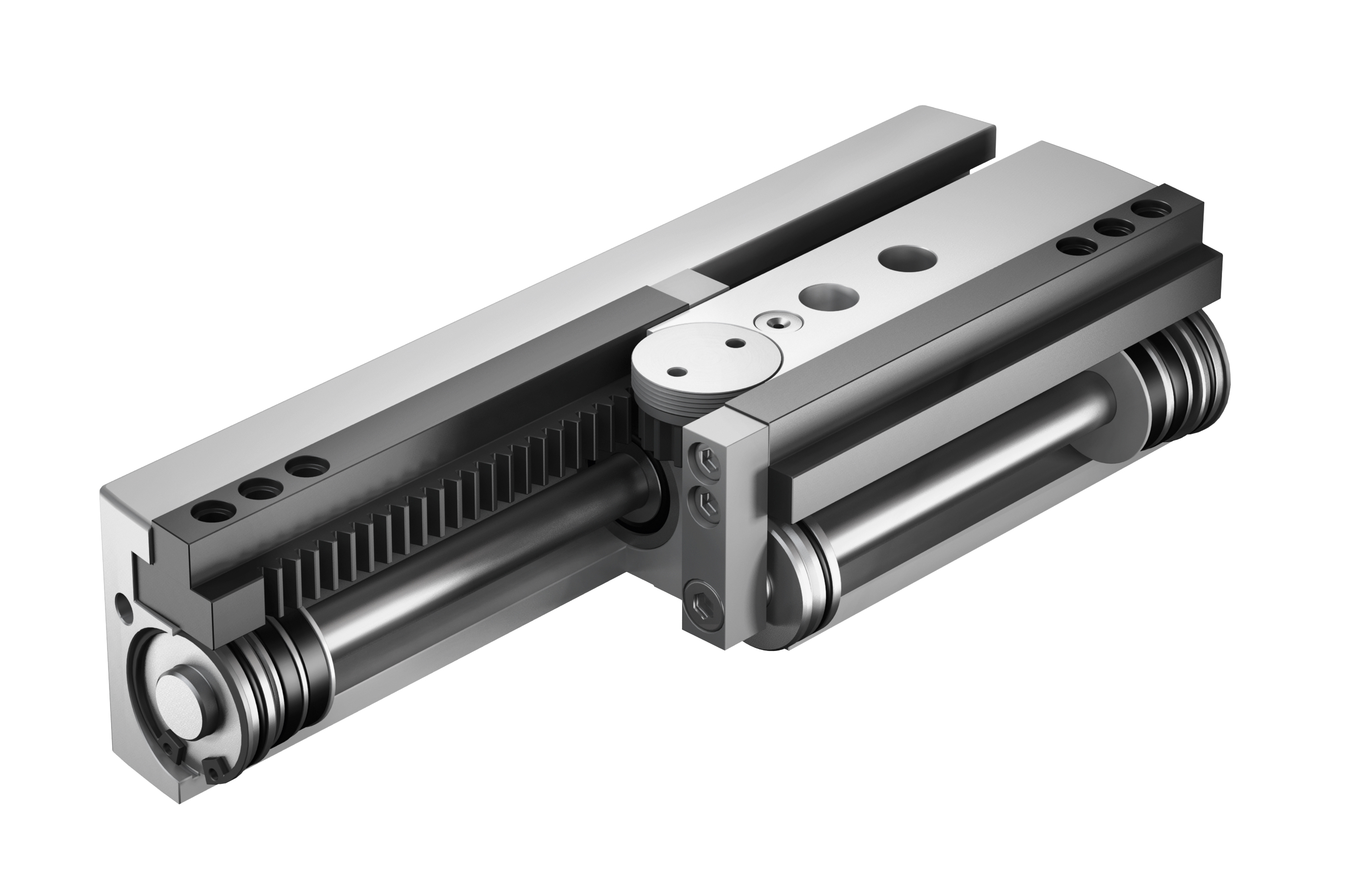
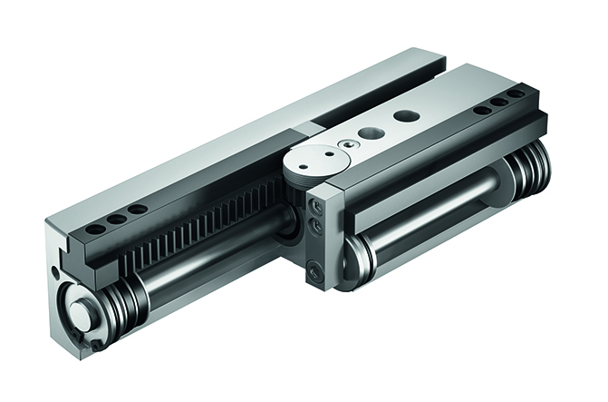
One rack-and-pinion variation is based on a roller pinion. These ultra-quiet rack-and-pinion sets have a pinion of bearing-supported rollers instead of a spur gear. Rollers ride the rack-tooth surfaces for 99% and repeatability to about 2.5 μm from one direction (or better than 5.8 μm from both). Manufacturers also make the rollers with meshing geometry to trace paths tangent to tooth faces. So, the rollers glide into engagement with the rack teeth, which eliminates the wear and inaccuracy from sliding friction and tooth slap of some rack-and-pinion sets.
No matter the version, the benefits of rack-and-pinion sets are that they can operate without enclosures or protective covers; they are efficient to 98% or better; and many exhibit backlash of 1 arc-min or less. Another strength is that they’re often less expensive than comparable linear motors when stroke lengths are long …
…. so that a rack-and-pinion set may cost half of what a linear motor costs, especially for many-meter strokes.
Rack-and-pinion sets sometimes perform better than ballscrew actuators because they’re not affected by adjacent bearings, couplings, or bores; they’re also immune to stiffness degradation, even over long lengths.
What’s more, as with any gear-based power transmission, rack-and-pinion sets come in several gear versions to satisfy various application requirements. For example, some helical-toothed racks sport helix angles engineered for quiet operation (with a high tooth-contact ratio) even under high loads at high speeds.
For more information on rack-and-pinion sets, also visit our sister site:
linearmotiontips.com/category/linear-actuators
Rack-and-pinion installation is straightforward. The racks mount on flat surfaces, and many versions sport forgiving designs and mounting features to maintain performance without perfect assembly. Even so, misaligned or improper mounting can damage sets and the attached gearmotor’s bearings. One common mistake is to put the motor-driven pinion too far from the rack. Here, design engineers should ensure that the pinion-to-rack distance is set to the manufacturer’s recommendation and that the rack and motor-driven pinion is perpendicular to the rack within tolerances.
Addressing the issue of backlash
Manufacturers often preload rack-and-pinion sets to boost stiffness and eliminate backlash. There are a few ways to do this. One option is to run twin pinions concurrently, with a slave pinion that gently opposes the drive force. This setup usually reduces efficiency, but boosts machine dynamics and stiffness.
A more sophisticated variation of this approach is to use the motion controller to apply preload electronically. Such controls maximize preload but reduce opposing slave-pinion force when the drive pinion accelerates. During constant-speed strokes, the slave pinion mirrors the action of master pinion, and the two drive in tandem. When the axis decelerates, the slave pinion engages the opposite tooth flank, increases force opposing drive force, and helps slow the load.
Leave a Reply
You must be logged in to post a comment.