
 Updated April 2015. || Driving linear-motion applications with pneumatic actuators (or air cylinders) is a relatively easy and inexpensive approach. The actuator technology has existed for more than 50 years, but better piston seals and rod wiper seals (of modern materials) make pneumatic actuators more resilient and efficient than ever. These seals reduce leakage and withstand extreme temperatures to let engineers use the actuators in more environments.
Likewise, surfaces with permanent lubrication, servo-pneumatic controls, improved corrosion resistance and air-cushioning features make pneumatic actuators more useful than ever.
To review, pneumatics is the technology of compressed air. However, in some circles, it’s more fashionable to refer to it as a type of automation control. Pressurized gas—generally air that may be either of the dry or lubricated type—is used to actuate an end effector and do work. (More after the jump.)
End effectors can range from the common cylinder to more application-specific devices such as grippers or air springs. Vacuum systems, also in the pneumatic realm, use vacuum generators and cups to handle delicate operations, such as lifting and moving large sheets of glass or delicate objects such as eggs. Pneumatics is commonly used in industries that include medical, packaging, material handling, entertainment and even robotics.
Also visit our sister website pneumatictips.com for a full library of specifics.
By its nature, air is easily compressible, and so pneumatic systems tend to absorb excessive shock, a feature useful in some applications. Most pneumatic systems operate at a pressure of about 100 psi, a small fraction of the 3,000 to 5,000 psi that some hydraulic systems see. 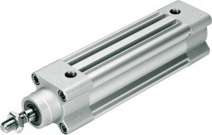 So, pneumatics are generally used when much smaller loads are involved.
A pneumatic system generally uses an air compressor to reduce the volume of the air, thereby increasing the pressure of the gas.
The pressurized gas travels through pneumatic hoses and is controlled by valves on the way to the actuator. The air supply itself must be filtered and monitored constantly to keep the system operating efficiently and the various components working properly. This also helps to ensure long system life.
In recent years, the control available within pneumatic systems (thanks to advanced electronics and componentry) has increased a great deal. Where once pneumatic systems could not compete with many comparable electronic automation systems, the technology today is seeing a renaissance of sorts.
Pneumatic actuator operation
Many industrial applications require linear motion during their operating sequence. One of the simplest and most cost effective ways to accomplish this is with a pneumatic actuator, often referred to as an air cylinder. An actuator is a device that translates a source of static power into useful output motion. It can also be used to apply a force.
Actuators are typically mechanical devices that take energy and convert it into some kind of motion. That motion can be in any form, such as blocking, clamping or ejecting.
Pneumatic actuators are mechanical devices that use compressed air acting on a piston inside a cylinder to move a load along a linear path. Unlike their hydraulic alternatives, the operating fluid in a pneumatic actuator is simply air, so leakage doesn’t drip and contaminate surrounding areas. There are many styles of pneumatic actuators, including diaphragm cylinders, rodless cylinders, telescoping cylinders and through-rod cylinders.
The most popular style of pneumatic actuator consists of a piston and rod moving inside a closed cylinder. This actuator style can be sub-divided into two types based on the operating principle: single acting and double acting.
Single-acting cylinders use one air port to let compressed air enter the cylinder to move the piston to the desired position, as well as an internal spring to return the piston to the “home” position when the air pressure is removed.
Double-acting cylinders have an air port at each end and move the piston forward and back by alternating the port that receives the high pressure air.
In a typical application, the actuator body is connected to a support frame and the end of the rod is connected to a machine element that is to be moved. An on/off control valve is used to direct compressed air into the extended port while opening the retract port to atmosphere. The difference in pressure on the two sides of the piston results in a force equal to the pressure differential multiplied by the surface area of the piston.
If the load connected to the rod is less than the resultant force, the piston and rod will extend and move the machine element. Reversing the valving and the compressed air flow will cause the assembly to retract back to the “home” position.
Pneumatic actuators are at the working end of a fluid power system. Upstream of these units, which produce the visible work of moving a load, are compressors, filters, pressure regulators, lubricators, on/off control valves and flow controls. Connecting all of these components together is a network of piping or tubing (either rigid or flexible) and fittings.
Pressure and flow requirements of the actuators in a system must be considered when selecting upstream system components to ensure good performance. Undersized upstream components can cause a pneumatic actuator to perform poorly, or make it unable to move its load.
Pneumatic cylinder selection
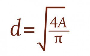
When selecting any air cylinder, it’s important to properly match the cylinder to the application, particularly in terms of required force. The theoretical force available in the actuator is the piston surface area multiplied by the supplied air pressure. Spring force must be subtracted from this value for single acting cylinders. The actual force applied to the load will be 3 to 20% less due to pressure losses in the system. When the required piston surface area (A) is known, the bore diameter (d) can be found by the formula:
The required travel of the machine element determines stroke length driven by the actuator. The final selection criterion is the cylinder mounting arrangement, and the resulting configuration.
There are myriad pneumatic-actuator configurations available from various manufacturers. The more common ones include rigid nose or tail mount, trunnion mount, rear pivot mount and foot mount. Once the basic actuator size and configuration are known, other options, such as end-of-stroke cushions or special seals, should be considered. In some applications, position detection switches are required, typically accomplished with a magnetic piston and switches.
Several factors, such as system contamination, corrosion, minor leaks and wear, affect the available air pressure and flow used to drive the actuator. Engineers should size the actuator and fluid-power system so as not to waste energy, with a margin added to account for minor reductions in pressure and flow.
Leave a Reply
You must be logged in to post a comment.