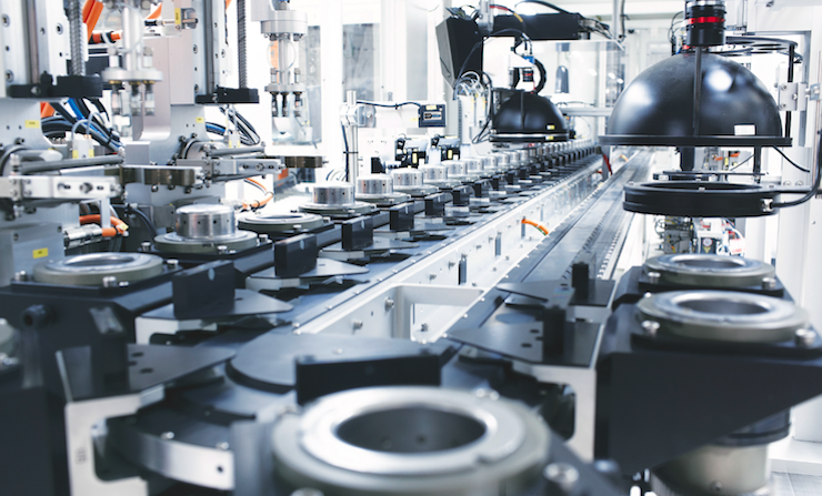
Scalable PC-based automation, robust network solutions and open camera standards allow machine vision to ditch black boxes and increase throughput.
Daymon Thompson
U.S. Software Product Manager
Beckhoff Automation LLC
Machine vision has become indispensable for many tasks in quality inspection, track-and-trace and more. As costs decrease and capabilities increase, practically any machine in any industry stands to benefit. But image processing suffers from high latency and less-than-ideal performance due to one critical flaw: It typically remains separate from the controls environment. Standalone smart cameras and either a separate high-performance computer or standalone vision controller each require specific configuration tools and programming languages. This can make companies dependent on external vision specialists for all changes, along with increased system complexity and costs.
From a technical standpoint, standalone vision hardware acquires an image and, only after processing, communicates the results to the controller via a fieldbus or communication protocol. Communication between image processing and the control system is often application specific and prone to error. The controller must wait to process those results in the next PLC cycle, then decide what to do with the results. This delay can reduce throughput or cause other issues for applications combining motion control and vision. Similarly, traditional PC-based vision solutions offer greater CPU and hardware availability for vision algorithms generally, but external processes, such as the OS, affect processing and transmission time.
But the times, and tech, are changing. Engineers today can run motion control, safety technology, measurement technology and robotics, among many other functions, on one machine controller versus multiple black boxes. Contemporary automation vendors are applying the same integrated approach to vision. Implementing all functionality in one engineering environment and runtime removes the standard barriers and boosts performance.
Integrated method for enhanced image processing
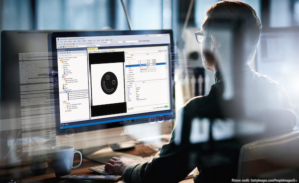
The integrated method involves completely integrating vision into a scalable Industrial PC (IPC) platform. Machine operations benefit in several ways, including deterministic reactions to results and no additional communication of results. Integrating vision algorithms and camera configuration into the same tool as the configuration of fieldbuses, motion axes, robotics, safety, and HMI is equally beneficial. TwinCAT Vision software, for example, places vision in the real-time context. By executing all algorithms on one deterministic, multitasking and multi-core CPU real time, vision, PLC and motion control are consistently synchronous.
By storing images in PLC memory, it’s easy to access and display the current image on the HMI without having to store to an intermediary file. This could be the raw incoming image or any image at a current intermediary vision algorithm processing step. Not only images should be displayed in the HMI, but also, for example, the configuration of vision or camera parameters. This lets the end users of the system access vision application parameters to adapt them to the respective conditions.

Fully integrated image processing solutions let engineers use known function blocks or IEC 61131-3 languages for programming and setting camera parameters. By removing the need for proprietary graphical languages, C++/C# and special configuration tools, machine builders save substantial effort and cost. PLC function blocks can, for example, change the state of the camera or trigger the camera for a new image. With this method, controls engineers who are familiar with Structured Text (ST), Sequential Function Chart (SFC), Ladder Logic (LD) or Continuous Function Chart (CFC) remain in control of the vision system and the entire machine.
Plus, moving machine vision away from black box systems and into the real-time environment allows watchdogs to monitor the timing of image processing functions. Image processing algorithms, due to the different image information, need different lengths of time to calculate, which can create throughput issues on production lines. For example, in a continuous flow process, the line should not – and typically cannot – slow down because there is more product grouped than usual. Even though this situation requires more time to review images in the vision system, attempting to stop product flow could be disastrous. With effective watchdogs, the vision algorithms can stop processing an image and return any partial results available.
Scalable processing power key to IPC
PC-based automation offers many options for scalable connectivity and computing power in applications with machine vision. Connectivity options in modern IPCs enable, for example, easily adding 10-plus network interface cards to allow individual communication channels for each camera to efficiently transfer the image to the PC for processing. This eliminates expensive switches, which can induce unnecessary latency and complicate wiring.
The IPC performance spectrum begins with cost-effective platforms and scales all the way up to many-core machine controllers with 40 processor cores. Having such a range is ideal for selecting the right computing power for individual image processing projects. Modern industrial control systems are architected from the ground up to harness the scalability of PC processors from single to many cores. Vision systems integrated into powerful PC-based control systems can also leverage the multi-core capabilities.

To make multi-core and core isolation implementation extremely easy for the programmer, configuration on some IPC platforms simply involves allocating “job tasks” to the cores. These tasks, which should be used for vision algorithms, are then grouped into a “job pool.” As vision is executed in the control system, the algorithms that can take advantage of parallel processing are automatically split between the multiple cores. They process in parallel, bring the results back together and present them to the PLC and the image algorithm’s results variable(s).
In this way, programmers need not worry about multiple cores, multiple threading or multiple tasks. They only need to implement the machine control logic and vision code, which allows the system to handle the multi-core processing on its own.
GigE standard establishes networking for vision systems
Integrated image processing on a powerful IPC first requires transmitting the image captured from the vision sensor to the controller. GigE Vision, a standardized and efficient communication protocol, makes this possible. This common industrial camera standard is based on Gigabit Ethernet with scalable speeds. There are no requirements for extra connectivity hardware and camera cables can extend up to 100 m.
A wide-ranging group of companies from every sector within the machine vision industry worked to develop the GigE standard, and now the Automated Imaging Association (AIA) maintains it. The original purpose was to establish a standard that would allow camera and software companies to seamlessly integrate their solutions on Gigabit Ethernet fieldbuses. GigE is the first standard that lets images be transferred at high speeds over long cable lengths.
While Gigabit Ethernet is a standard bus technology, not all cameras with Gigabit Ethernet ports are GigE Vision compliant. In order to be GigE Vision compliant, the camera must adhere to the protocols established by the GigE Vision standard and must be certified by the AIA. It’s crucial to check this when specifying components for a vision application.

Manufacturers of cameras with the GigE Vision interface provide a configuration description in GenApi format. Integrated machine vision configuration tools read the parameters and make them available to the user in a clearly arranged manner. In this way, configuration changes, such as adjusting the exposure time and setting a region of interest, can happen quickly and easily. In terms of complexity, the parameterization of a camera for a vision application is comparable to the parameterization of a servo drive.
Advantages of EtherCAT
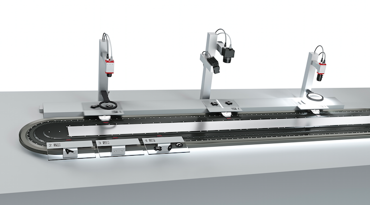
PC-based automation delivers inherent benefits from core controls functionality such as real-time PLC and access to many fieldbuses, including the EtherCAT industrial Ethernet system. Due to the high determinism of the EtherCAT protocol and device synchronization via distributed clocks, extremely precise trigger timing and timestamp-based output terminals can send a hardware trigger signal with microsecond-level accuracy to the camera. Because everything takes place in real time in a highly accurate temporal context, image acquisition and axis positions, for example, can synchronize with high precision – a task that PLC programmers frequently handle. Many cameras can also send output signals at previously defined events, such as the start of image capture. These signals can be acquired with a digital input terminal on the EtherCAT network and then used in the PLC for precise synchronization of further processes.
Specially developed vision lighting controllers triggered via EtherCAT enable flash lighting with pulses at 50 µsec. Each individual flash can be triggered with great precision by the controller via distributed clocks and timestamping. This ensures that products on a conveyor, for example, reach the exact position before each trigger event. Synchronicity is ultimately a major factor driving the integration of vision technology inside the machine controller and fieldbus. This gives an EtherCAT lighting device high cycle synchronicity, because it’s triggered in the same cycle as the camera recording or the robot movement.
Image processing will continue to grow more important and, in many situations, replace sensors as the price point lowers. By standardizing on PC-based automation with scalable controller hardware and a combined real-time and engineering environment, engineers can future-proof vision-intensive applications.
Beckhoff Automation LLC
www.beckhoffautomation.com/vision


Leave a Reply
You must be logged in to post a comment.