One of the best technologies for achieving extremely small, precise movements is the piezo motor. Based on the piezo actuator – layers or stacks of piezo elements that produce motion through the reverse piezoelectric effect – the piezo motor incorporates mechanical elements to produce strokes of several hundred millimeters or more. And while most piezo motors are designed to produce linear motion, there are several types that can also produce rotary motion, making them suitable for applications such as optical equipment and measuring devices.
Linear ultrasonic piezo motors incorporate a piezo actuator, a friction component, and a runner. To achieve rotary motion, several piezo actuators are arranged in a ring-shaped formation, sometimes referred to as the “stator,” and the linear runner is replaced with a ring-shaped rotor. When high-frequency AC voltage is applied to the stator, it causes wave-like, ultrasonic vibrations in the piezo actuators. The vibrations of the stator are transmitted to the rotor through the friction element, causing the rotor to turn at high speed.
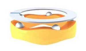
Image credit: Physik Instrumente
A variation of this design uses two ultrasonic piezo actuators, mounted and preloaded tangentially on a friction ring. With each oscillation of the actuators, friction tips contact the ring and advance it, causing it to rotate.
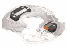
Image credit: Physik Instrumente
Another piezo technology that can produce rotary motion is the walking type piezo motor. These designs use multiple piezo bending actuators (or a combination of clamping and shear actuators) to rotate a ring. The piezo actuators are synchronized in pairs – often referred to as “legs.” When voltage is applied, the first pair of legs extends, grips the ring, and moves it in the desired direction. At the same time, the second pair of legs retracts away from the ring and moves in the opposite direction. On the next activation, the first pair of legs retracts and moves backwards while the second pair extends to make contact with the ring and move it further along its direction of rotation. Although each “step” is just a few microns, operating at high frequency provides thousands of steps per second, for high rotational speeds.
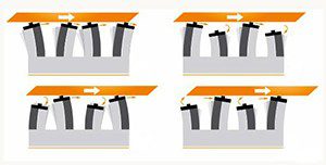
Image credit: MICROMO
Piezo inertia motors (commonly referred to as “stick-slip” motors) can also be configured to produce rotary motion. While inertia motors don’t produce rotary motion directly, they’re often used to drive very fine pitch screws. In this design, jaws attached to each end of a piezo actuator engage with the screw, 180 degrees apart. As the actuator rapidly expands and contracts, the jaws turn the screw.
Image credit: Thorlabs, Inc.
Leave a Reply
You must be logged in to post a comment.