Industrial robots, conveyors, wind turbines, machine tools, packaging machines and pumps are just some of the places you’ll find torque limiters.
By Lawrence Kren • Contributing writer
Torque limiters actuate on the order of milliseconds to prevent overload, shock, and torque spikes that could otherwise damage components or shorten operating life. They also serve in equipment needing specific torque levels. A machine that installs bottle caps, for example, must apply sufficient torque to tighten a cap but not break the bottle.
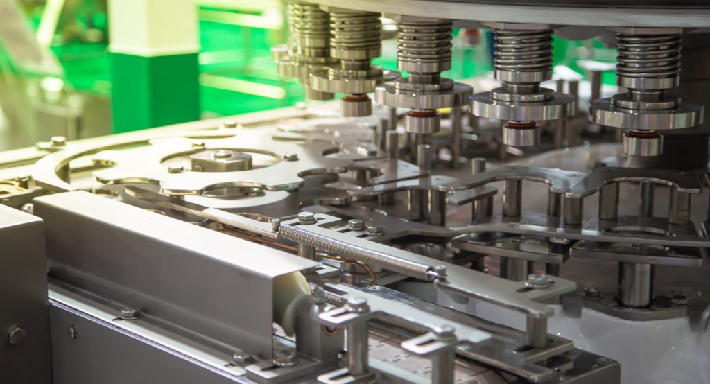
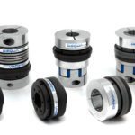
Torque limiters span a wide range of rated torque — from much less than 1 N-m to over 10,000 kN-m. They come in three basic types: friction, ball detent, and shear pin.
Friction torque limiters
Friction torque limiters slip in response to an overload event and fully engage other times. A spring-actuated frictional torque limiter applies spring force to opposing friction surfaces on input and output hubs. Exceeding a set torque level causes the surfaces to slip relative to one another, limiting power transmission. Pneumatic and hydraulic actuated torque limiters may also use friction material to transmit torque but rely on pistons or diaphragms moved by air or fluid pressure to force friction surfaces together and adjust torque limits.
Friction material may be dry or in an oil bath. Generally, higher-capacity units that dissipate more energy (or those designed to continuously slip) use oil cooling to maintain friction material at safe operating temperatures.
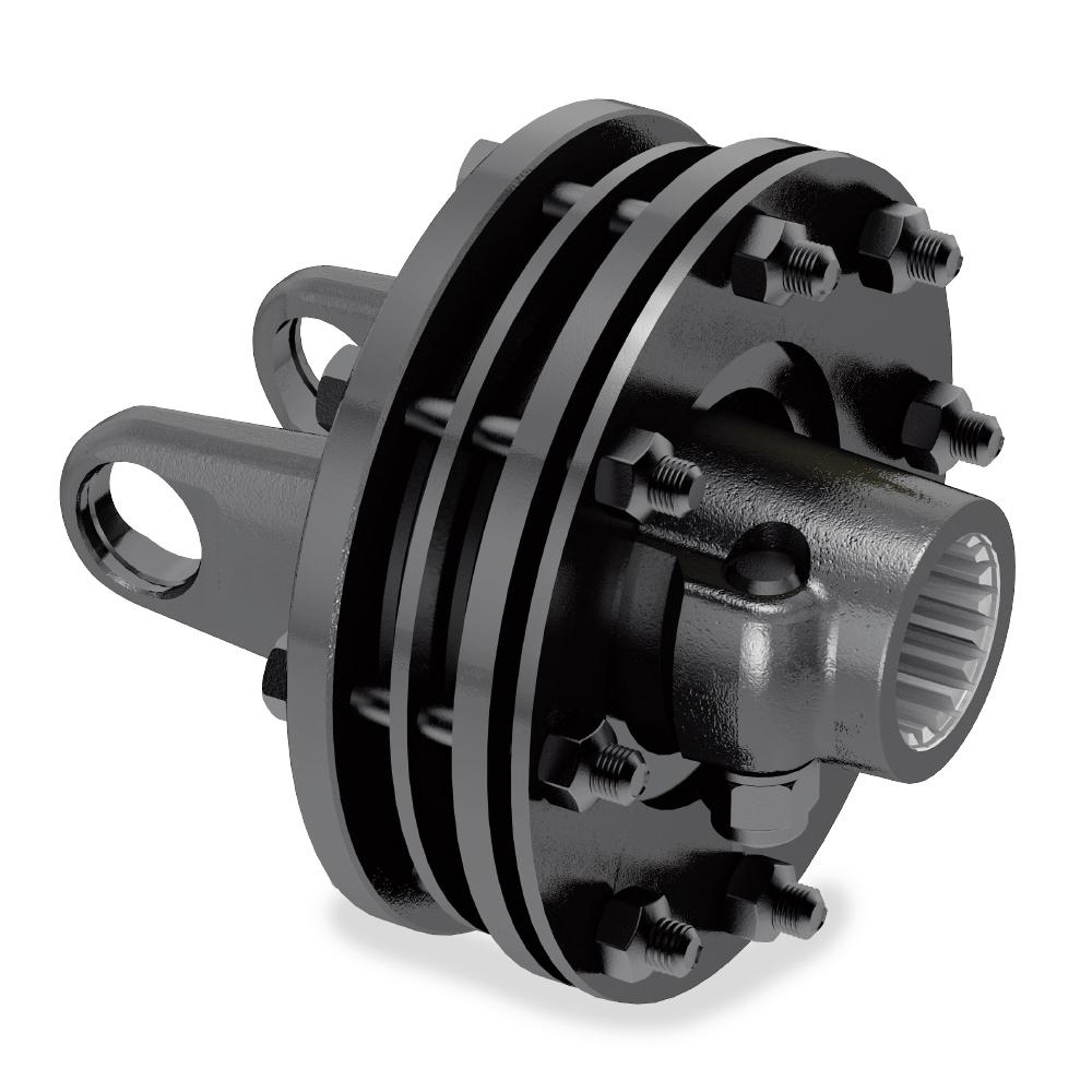
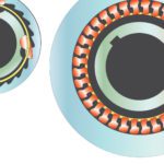
These designs have a couple drawbacks. Friction-style torque limiters, dry or wet, wear over time and may need maintenance or eventual replacement. Debris generated by friction material in open, dry designs make them unsuitable for certain environments such as in clean rooms. Available sealed units contain the wear debris. In contrast, torque limiters employing permanent magnets that couple loads through magnetic flux have no friction material to wear or produce debris. Some electromagnetic types also work without friction material but need external power to generate magnetic flux.
Ball-detent torque limiters
Ball-detent torque limiters may be automatic or manually resettable, while hybrid models combine both automatic and manual reset functions in a single unit.
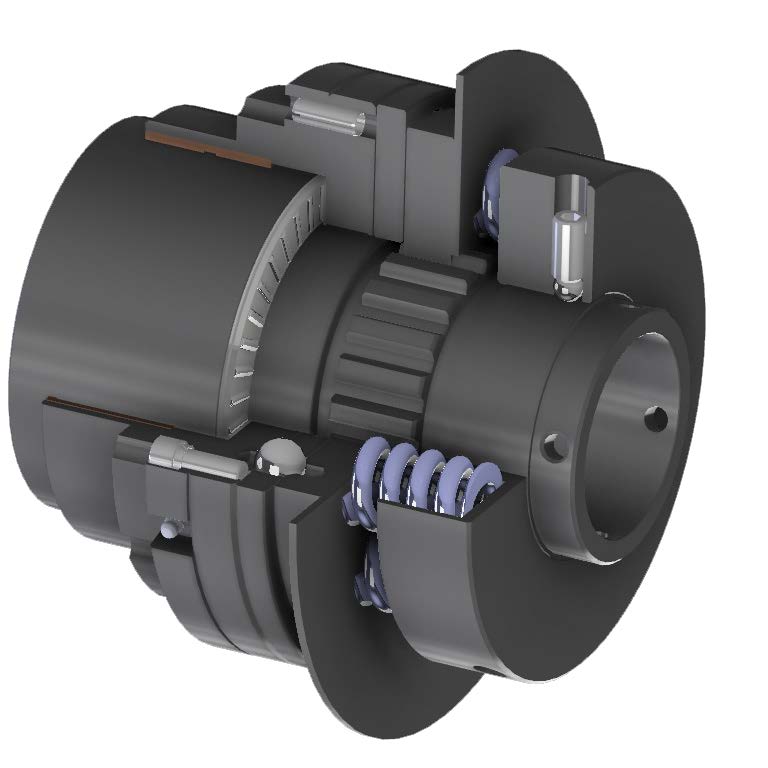
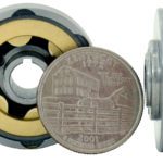
Detent-style torque limiters transmit nominal torque then fully disengage when they see excessive torque levels, and freewheel until reset. A typical design uses springs to push bearing balls into pockets (detents) on a drive flange that transmits torque. Exceeding a set value overcomes spring force, which in turn dislodges the balls and uncouples the load. Depending on the configuration, an overload trip may need that an operator manually reset the device, while other designs automatically reset when the overload condition clears. Some units reset in multiple clock positions, while those used in timed mechanisms reset to the same clock position each time. Pneumatic or hydraulically actuated units often incorporate sensors that detect an overload condition and cut pressure to decouple the load.
Shear-pin torque limiters
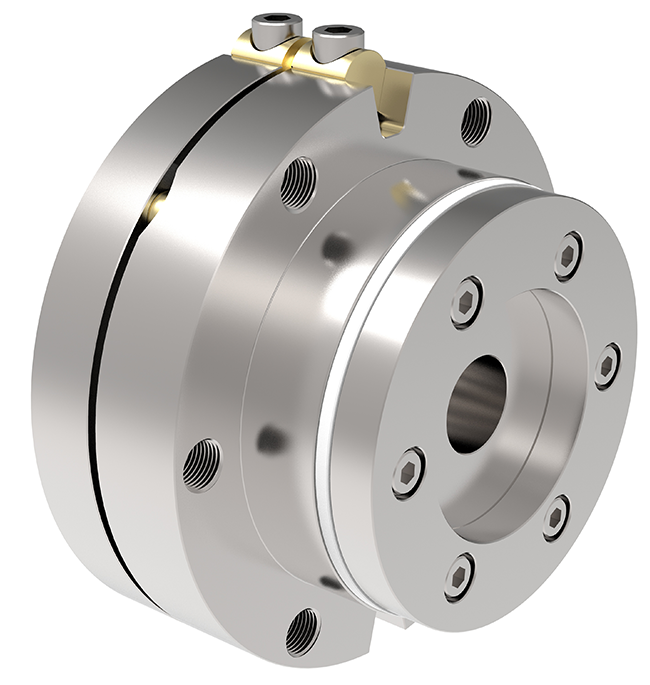
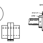
A simpler, manually resettable design shears a replaceable pin when overloaded. These shear-pin torque limiters have been largely replaced by ball-detent types because the latter are easier and quicker to reset, which boosts machine uptime. Plus the torque level at which ball-detent types actuate or trip tends to be more repeatable than that of shear pins. Applications needing extremely high torque ratings, such as mining equipment, however, still rely on shear-pin torque limiters.
The key parameter of trip torque
Regardless of the application, trip torque TP is a key metric when choosing a torque limiter:
TP = SF x TL
Where TL = Shaft torque, N-m = 60,000 ⋅ P/(2π ⋅ n)
P = Transmitted power, kW
n = rpm
SF = Service factor
Service factor scales with severity of operating conditions. A typical value for normal startup and stops is 1.25, while heavy shock and reversing loads may use a 1.5 service factor. Startup torque often exceeds running levels, so torque limiters placed in line with these drive components should be sized to provide ample margin without excessive slipping yet protect downstream components from overload. Best practice places a torque limiter as close to the load as possible, preferably upstream of high-value, torque-sensitive components.
For startup, trip torque must at least equal the torsional load from acceleration and applied load:
Tp ≥ α ⋅ JL + TAL
Where α = Angular acceleration = ω/t, rad/sec2
ω = Angular velocity, rad/sec
t = Acceleration time, sec
JL = Load moment of inertia, kg-m2
TAL = Applied torque, N-m
Trip torque accuracy and backlash are other important considerations. In general, torque limiter manufacturers specify ±5 to 10% accuracy for repeated trips. Numerous models have minimal or even zero backlash. Low backlash is especially important when torque limiters reside in-line with positioning equipment or applications that see reversing loads.
One final note: All torque limiters, regardless of type, add inertia to a system. Be sure to follow established guidelines for inertia matching so motion system performance doesn’t suffer.
Motion Control Tips | motioncontroltips.com



Leave a Reply
You must be logged in to post a comment.