
Updated November 2018 by Lisa Eitel || Torque limiters protect equipment or loads from excessive torque. In essence, they are used to shut down a machine and dissipate any rotational energy without causing damage to the machine. Often, systems operating at low speeds can develop a large quantity of torque. In the event of a malfunction, this excess torque can damage machine components such as gearing, couplings, and motor or drive shafts. A torque limiter will prevent damage by limiting the amount of torque to some preset level.
Some consider mechanical torque limiters outdated because there are other ways to control torque overload, most notably via electronic current limitation of the motor. While this may work in some cases, as machinery becomes more dynamic, the inertia of moving parts becomes more critical. So, for instance, it’s possible to abruptly decelerate a rotating mass through unintentional blockage or the application of a dynamic braking system at a rate faster than the drive would normally accelerate.
This can create torque overload through the reflected inertia which is completely independent of the electronic system and so can easily exceed the peak torque rating of the motor. While older and bulkier designs may be out of the question, these modern mechanical torque limiters offer a high level of sensitivity and accuracy, with increasingly smaller impact on the size, mass, balance, and power consumption of the drive system.
There are fundamentally two types of torque limiter technologies, the disconnect type and the slip type. Disconnect torque limiters, as the name implies, physically disconnect the drive from the load. Several methods exist for the disconnecting process. The shear pin method actually destroys the pin joining the load with the drive. Another common method is via magnetic disconnection using permanent magnets. The common feature of disconnect type torque limiters is that they permanently separate the drive and driven shaft and require a manual re-engagement.
Slip type torque limiters work by letting the drive shaft run faster than the driven shaft. It effectively “slips” at some preset torque setting and reengages when the torque falls below the limit.
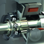
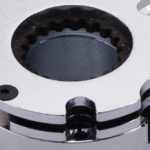
Here’s how the simplest versions work: Rollers (usually balls) are sandwiched between two component halves — and rest in mirror-image detents machined into these halves. Usually springs hold the halves together. The motor-driven side transmits torque to the load half called the thrust or pressure flange, and the whole assembly rotates in unison unless there’s an overload. In such situations, the overload-clutch halves overcome the axial spring force and repel apart. The rollers come free of their detents and roll to continue onward or resettle into the next detent pair when the jam or other overload is removed.
The most important factor in selecting a torque limiter is determining the proper torque rating, which will help determine the proper torque limiter size. Torque limiters are ideally installed as physically close to the point of impact or overload as possible in order to enhance sensitivity.
Torque limiters are often used in conjunction with a proximity sensor to detect the movement of an external ring around the disengaging safety clutch, and then trigger an e-stop condition in the machine. Free wheeling safety clutches will permanently separate the drive and driven shaft hubs of the coupling, requiring a manual re-engagement. This cuts back significantly on potential wear between the two halves of the torque limiter as they ratchet against each other.
Overload clutches (torque limiters) for guaranteed actuator protection
Torque limiters are sometimes called overload clutches. That’s most common when they’re pre-integrated into designs. Case in point: The new Warner Linear B-Track K4x dc-motor-driven ballscrew actuator (which delivers 4,000 lb load capacity) includes a ball-detent overload clutch. The actuators excel where designs can’t use fluid-power cylinders — on solar panels, off-highway equipment, scissor and dump box lifts, and mower and tractor lifts, for example.
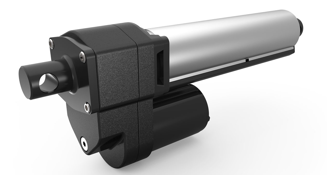
Its overload clutch setting is at 25% over the actuator’s rated dynamic load. Main strengths here are simple and accurate disengagement at a preset torque.


Leave a Reply
You must be logged in to post a comment.