
Servomotor-driven machinery abounds in today’s automated applications. These designs typically require high speeds for top throughput, dynamic operation for nimble positioning, and (in many cases) quick reversals for indexing. So it’s key to have some means to:
Protect the servomotor from damage by sudden load changes, over-torque conditions, or shock due to machine issues. The latter can include errors in programming, mechanical or feedback malfunctions, faulty braking, and machine-operator mistakes.
Protect the power-transmission assembly (including gearing and couplings as well as ballscrew, belt, or other drive components) from the behavior of its own inertia, motor-rotor inertia, and (reflected) load inertia — and even leverage system inertia — in atypical situations.
That’s because the processes that servo-driven machinery execute usually involve either expensive workpieces or high volumes … mission-critical operations with equipment that is itself costly. Such processes are intolerant of unexpected downtime from shock and jam-induced failures of subcomponents.
Overload protection includes often-complementary electronic and mechanical means.
Consider how servosystems can include electronic fusing, current limiting, and other modes of electronic overload protection to address crashes and sudden axis stops. Such protection uses controls (such as PLCs or servo drives) and feedback to track the axis state — monitoring and controlling motor-winding temperatures, current and voltage, as well as output force or torque and position in some cases.
Where applicable, these modes of electronic overload protection also complement the use of powerful low-inertia servomotors to boost overall performance and efficiency. Then when there are issues with any monitored parameters (especially those that indicate total axis jams) motion controls trigger preset corrections with motor-drive shutdowns, brake engagement, or other commands to trigger a motor-based response.
But one limitation of electronic torque limiting is that it’s not always quick enough to prevent machine or workpiece (or process) damage. That’s especially true for addressing inertial effects on dynamic motion axes; the masses of the mechanical components exert behavior that electronic corrections generally don’t resolve. In other words, the reliance of electronically programmed torque limiting on motor operation to correct problems leaves no immediate mode of addressing the action of components’ rotating masses (inertia) downstream.
In contrast, mechanical torque limiters provide near-instantaneous response (breaking free in just 1 msec in some cases) to issues. When installed at the right location in the drivetrain, these disconnect system inertia from the locked portion of the axis and let the drivetrain coast to a stop. That helps prevent damage in the first dozen or so milliseconds of machine-axis crashes or over-torqued conditions, when the most damage typically occurs.
Torque limiters used this way are also called torque-overload devices, safety couplings, overload clutches, and slip clutches. Note: Though this may be just a matter of semantics, torque limiters are technically not clutches because they are not built for continuous slipping. Related (though also nonequivalent) technologies are mechanical overrunning clutches that use wrap-spring, roller ramp, ratcheting, and cam action for one-way engagement.
Servo-system inertia in context of torque limiters
Recall that according to Newton’s second law for rotating systems, applying torque τ (in N∙m) to a mass induces angular velocity ω in rad/sec — with acceleration inversely proportional to the moment of inertia J (in kg∙m2) of that mass. Power P = τ ω = τ 2π∙n — with 1 rad = 360° ÷ 2π∙n and n = revolutions per sec. Also:
![]()
Where t = Time to accelerate or decelerate (sec) so that stopping time and torque τ are inversely proportional.
Often, the torque τ of a sudden jam or braking (inducing an axis stop within just a few milliseconds) is quite high … to 100,000 N∙m/sec is not atypical … and in fact, overload via reflected inertia (from the mass of all the load and power-transmission components on the axis) can easily exceed the servomotor’s peak-torque rating.
Though machine axes can be built with torque ratings that allow for some momentary exceedances, a torque limiter in such a design can disengage at torques dangerously higher than continuous motor torque. These slip during shock loading of significant inertia-induced torque and not during startup or otherwise normal operation. Or the torque limiter (with the help of a speed sensor) can disengage the axis at some torque below peak motor torque and concurrently trigger a motor shutdown. When paired with electronic overload protection and installed where jams may occur (typically at the furthest reaches of axis actuation) still other mechanical torque limiters include a ring or other subcomponent to allow the mounting of proximity switches that in turn communicate overload conditions to a controller for electronic follow-up remediation.
Where axis cycle rates are aggressive for the application’s load inertia, the torque limiter may need to have expanded range and capacity. That’s certainly true where torque limiters protect against damaging levels of shock loading but allow system inertia to temporarily increase torque and power the axis through certain conditions, if that’s part of the design.
As mentioned, some servomotors are specifically engineered to have low (rotor) inertia; these often find use in high-performance applications having high inertia ratios of (reflected) load inertia to motor inertia — breaking the somewhat arbitrary rule of thumb that this ratio not exceed 5 to 10:1 or so. Search motioncontroltips.com for “servomotor inertia ratio” for more information on this. Also read the FAQ: Why does servomotor inertia matter?
Such motors exhibit quick deceleration (to stop from top speed in 20 msec, for example) but the inclusion of mechanical torque limiters is often required for wholly safe execution of dynamic tasks.
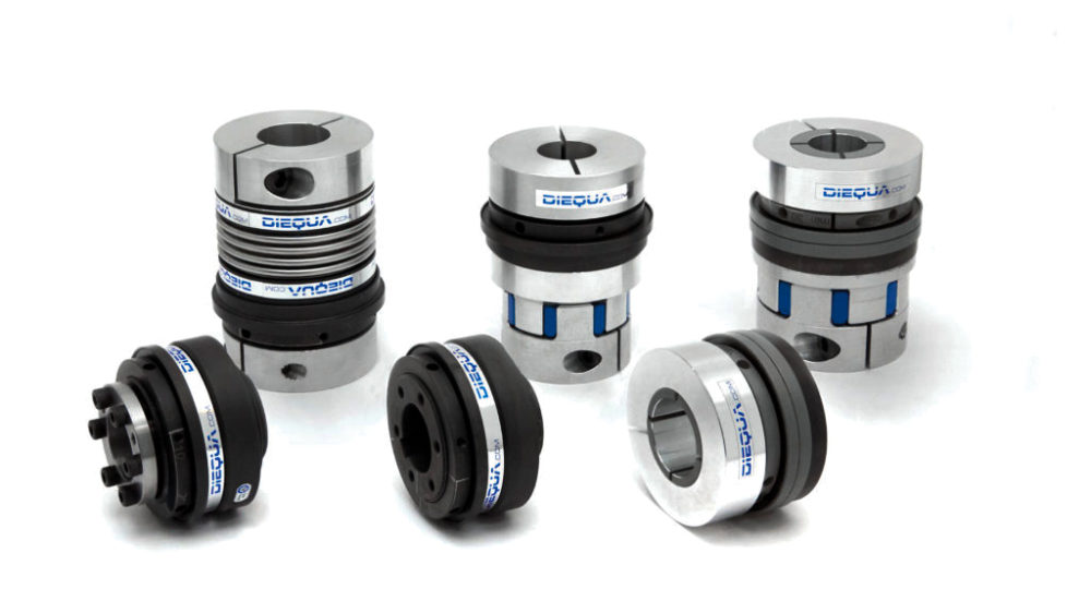
Torque-limiter variations for adding to servomotor-driven systems
Torque limiters are either releasable or continuously engaged. Releasable designs include ball-detent torque limiters (which are particularly common in servomotor applications), shear-pin limiters, permanent-magnet and loaded pawl-spring torque limiters, and sprag-engagement torque limiters.
Slipping torque limiters requiring no reset upon load correction include magnetic-hysteresis and magnetic-particle torque limiters as well as friction-disc torque limiters. During a machine-axis jam, these slip just enough to absorb inertia shock load and (as mentioned) trigger controls to let the motor stop.
When specifying torque limiters, look for availability of torque-specific models or those with some means of adjustment; backlash-free operation; and quantification of accuracy as a percent — ±4% of the trip torque, for example. Limiters billed as precision-tripping models will not exhibit lost motion (play). Torque limiters that integrate couplings also include misalignment-compensation values in degrees.

Leave a Reply
You must be logged in to post a comment.