
Although the back EMF waveform of a brushless DC (BLDC) motor is theoretically trapezoidal, in reality, inductance in the motor smooths the back EMF into a more sinusoidal shape. This is why BLDC motors can use either trapezoidal or sinusoidal commutation methods. While trapezoidal commutation is the simpler of the two methods, it produces significant torque ripple at each commutation step (every 60 degrees). Sinusoidal commutation eliminates the torque ripple inherent to trapezoidal commutation and provides smooth motion and precise motor control.
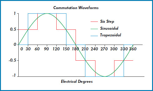
Image credit: Aerotech Inc.
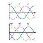
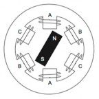
The basic premise behind sinusoidal commutation is to provide each of the motor windings with currents that vary sinusoidally as the motor turns. The currents are phase shifted by 120 degrees, to match the orientation of the stator windings. The current space vector has constant magnitude and is always orthogonal to the rotor. (Recall that maximum torque is produced when the stator and rotor magnetic fields are orthogonal, or at 90 degrees, to each other.) A key to achieving sinusoidal commutation is the ability to accurately determine the rotor position. Since Hall devices provide only a rough measurement of rotor position, an encoder is typically used to provide rotor position information.
Based on the rotor position, two sinusoidal waveforms are created, 120 degrees phase shifted from each other. Multiplying these signals by the torque command produces amplitudes that are proportional to the desired torque. These commands are fed to the controller, which regulates the current in the motor windings. According to Kirchhoff’s current law, the sum of the three currents must be equal to zero, so the current in the third motor winding is the negative sum of the first two (to maintain a zero sum of the three), and therefore, cannot be controlled directly.
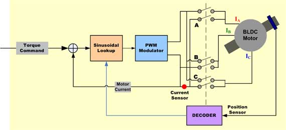
Image credit: Renesas Electronics Corporation
To see how this works, let’s look at the torque equation for a three-phase motor:
T = Kt * [IA * Sin(θ) + IB * Sin(θ +120) + IC * Sin(θ +240)]
Where:
T = torque
Kt = torque constant
IA, IB, IC = phase currents
θ = electrical angle of shaft
Because the phase currents are sinusoidal:
IA = M * Sin(θ)
IB = M * Sin(θ+120)
IC = M * Sin(θ+240)
Where M = motor current command with respect to the angle θ
Substituting, we get:
T = Kt * M * [(sin2(θ) + sin2(θ+120) + sin2(θ+240)]
Solving the trigonometric functions* gives us:
T = Kt * M * 1.5 * [sin2(θ) + cos2(θ)]
Since sin2(θ) + cos2(θ) = 1, the equation simplifies to:
T = 1.5 * Kt * M
This shows that torque is independent of the shaft angle, thus eliminating torque ripple.
The trigonometry to solve this equation gets quite complicated but if you’re interested in the full derivation, check out Appendix A of this Application Note from Galil Motion Control.
The downside of sinusoidal commutation is that it becomes inefficient at high speeds. The faster the motor turns, the higher the frequency of the sinusoidal signals, and controllers have difficulty tracking these high-frequency signals. Higher motor speeds also cause back-EMF to increase in both amplitude and frequency, making it more difficult for the motor to overcome.
Both of theses conditions result in disturbances to the current control loop and cause phase lag and errors in the currents. The result is that the current space vector moves away from the ideal (orthogonal) position relative to the rotor, and less torque is produced by a given amount of current.

Leave a Reply
You must be logged in to post a comment.