
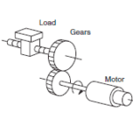
In any motor-driven system, the difference between the motor inertia and the load inertia will affect the system’s performance — especially its ability to accelerate the load quickly and efficiently.
While servo motors are the preferred choice for applications that specify a precise move profile, AC induction motors are often the better choice for applications where a rotating device (such as a fan, blower, or gearbox) needs to achieve a given speed within a certain amount of time and maintain that speed regardless of changes in the load.
In servo-driven motion control applications, we typically look at the inertia ratio — the ratio of the load inertia to the motor inertia — to give us an idea of how the motor will perform for the type of application and performance requirements (high acceleration, fast settling time, accurate positioning). Although inertia matching is less critical for induction motor applications than for servo-driven systems, inertia still plays an important role in the sizing and selection of an AC induction motor. This is because with rotating loads, the required motor torque is directly related to the inertia of the load.
![]()
T = torque required by motor
J = inertia of rotating load
α = angular acceleration of load
Note that inertia includes the inertia of the load (a fan, for example) plus the inertia of the motor and any other rotating components (such as couplings or pulleys) between the motor and the load.
Two definitions of inertia for AC induction motors
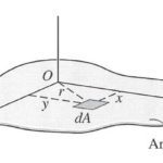
In motion control applications, inertia is generally given as J (as shown in the equation above) and is defined as “mass times radius squared.” However, in many rotating equipment applications, inertia is given as either WR2 or WK2 and is defined as “weight times radius squared.”
Notice that the inertia equations for induction motors use weight (which is a force) rather than mass. Also notice that the distance (radius) can be specified as either “R” (WR2) or “K” (WK2). R is the radius of the object, from its center to its outer edge. K is the radius of gyration, which is the distance from the point around which the object rotates, to the point at which the mass can be considered to be concentrated.
These expressions for inertia — WR2 and WK2 — are often used interchangeably, although R (radius) and K (radius of gyration) are rarely the same values. Here’s why…
If a hollow cylinder with extremely thin walls rotates around its axis, it’s reasonable to assume that the cylinder’s mass (weight) is concentrated around the outside circumference. So the radius of gyration for the thin-walled cylinder will be measured from the center to the outside edge of the cylinder. Thus the radius of gyration, K, is equal to the radius of the cylinder, R.
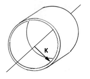
However, if the cylinder is solid and uniform, its mass (weight) can be assumed to be concentrated at a distance of 1/2 the radius. In this case, the radius of gyration is ½ of the radius (K = ½R).
Using inertia to determine torque and acceleration
The distinction between these two inertia equations, WR2 and WK2, is important because in AC induction motor applications, inertia is used to determine the motor torque required to achieve a desired speed within a given time.
![]()
T = acceleration torque (lb-ft)
W = weight of load to be accelerated (lb)
R = radius (or K, radius of gyration) (ft)
N = change in speed (rpm)
t = time to accelerate (s)
Note: 308 is a constant that incorporates the conversions from lbf to lbm, and from rotations per minute to radians per second
Inertia can also be used to determine the time the motor will take to reach a given speed with a defined acceleration torque.
![]()
This is important because induction motors draw very high current during start-up and acceleration, and high current for an extended period of time can damage the motor.


Leave a Reply
You must be logged in to post a comment.