
Inertia, or more specifically, inertia ratio, is one of the most important factors in sizing a servo system. Inertia is defined an object’s resistance to change in velocity, and in servo-driven systems, it can be used as a measure of how well the motor is able to control the acceleration and deceleration of the load. The yardstick by which this is judged is the inertia ratio, which is defined as the inertia of the driven component(s) divided by the inertia of the motor.
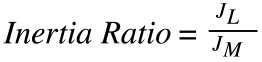
JL = inertia of load reflected to motor
JM = inertia of motor
An inertia ratio that is too low means the motor is likely oversized, leading to higher than necessary cost and energy usage. An inertia ratio that is too high means the motor will have a difficult time controlling the load, which results in resonance and causes the system to overshoot its target parameter (position, velocity or torque).
While it seems logical that an inertia ratio of 1:1 would be the goal, it’s not always achievable or cost-effective. Most servo motor manufacturers recommend that the inertia ratio be kept to 10:1 or less, although there are many applications that operate successfully at much higher ratios. The best inertia ratio for an application comes down to the dynamics of the move and the accuracy required.
How to calculate inertia of a drive system
Load inertia includes the inertia of all rotating parts, including the drive (such as a belt and pulley system, screw, or rack and pinion), the load being moved, and the coupling between the load and the motor.
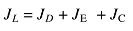
JL = inertia of load reflected to motor
JD = inertia of drive (ball screw, belt, rack & pinion)
JE = inertia of external (moved) load
JC = inertia of coupling
Manufacturers typically provide the inertia value (or a simple equation to calculate the inertia value) of drive systems, such as ball screws. But if the inertia value isn’t provided, it must be calculated manually. One of the most common ways to do this is to model the drive system as a shape for which the inertia equation is easily defined. Some common examples are solid cylinders and hollow cylinders.
Inertia of solid cylinder (screw or pinion)

Inertia of hollow cylinder (pulley)
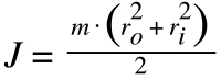
m = mass of cylinder
r = radius of solid cylinder
ro = outer radius of hollow cylinder
ri = inner radius of hollow cylinder
How to calculate inertia of a load
To determine the inertia of a screw-driven load, the effect of the screw’s lead must be taken into account.
Inertia of load driven by screw
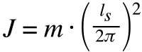
m = mass of load
ls = lead of screw
Note that this equation is based on the screw’s lead (expressed as inches or mm per revolution), not on the pitch (expressed as revolutions per inch or per millimeter).
When a load is driven by a belt and pulley system, the mass of both the load and the belt must be considered, since both of these components are being driven by the motor. Rack and pinion systems are treated similarly, with the mass of the pinion being added to the mass of the load.
Inertia of load driven by belt (or rack and pinion)
![]()
m = mass of load + mass of belt (or pinion)
Also, the radius in this case is the outer radius of the pulley, since this is the axis around which the belt and load are being rotated.
How to reduce inertia ratio
If the inertia ratio is too high, one way to reduce it is to add a gearbox to the system. In this case, the inertia of the load is divided by the square of the gear ratio.
Inertia of load with gear reduction
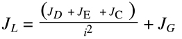
JG = inertia of gearbox
i = gear ratio
Note that the inertia of the gearbox is added to the system, but its addition is small compared to the reduction provided by the gear ratio, which has an inverse squared effect on the load inertia.
If you’re not done calculating, check out our list of engineering calculators.


Leave a Reply
You must be logged in to post a comment.