• Skip to primary navigation
  • Skip to main content
  • Skip to primary sidebar
  • Skip to footer
  • Advertise
  • Subscribe

Motion Control Tips

Automation • Motion Control • Power Transmission

  • News
    • Industry News
    • Editor Blogs
  • Controls
    • HMIs
    • PC-Based Controllers
    • PLCs + PACs
    • Stand-Alone Controllers
    • Software
  • Drives
    • Servo Drives
    • Stepper Drives
  • Encoders
    • Absolute Encoders
    • Incremental Encoders
    • Rotary Encoders
  • Mechanical
    • Bearings
    • Brakes + Clutches
    • Belt + chain
    • Couplings
    • Gears + Gearing
    • Lubrication
    • Shock + Vibration Mitigation
    • Springs + Rings + Seals
  • Linear
    • Actuators
    • Linear Motors
    • Linear Encoders
  • Motors
    • AC Motors
    • DC Motors
    • Brushless Motors
    • Gearmotors
    • Piezo Motors
    • Servo Motors
    • Stepper Motors
  • Systems
    • Conveyors + linear transport systems
    • Gantries + Stages
    • Rotary Tables
    • Grippers + End Effectors
    • Robotics
  • Networks
    • Connections + Sliprings
    • Fieldbuses
    • I/O
    • Sensors + Vision
  • Resources
    • FAQs
      • Motion Casebook
      • Motion Selection Guides
    • Suppliers
    • Video
You are here: Home / FAQs + basics / Electric motor fluting: What is it and what causes it?

Electric motor fluting: What is it and what causes it?

June 12, 2017 By Danielle Collins Leave a Comment

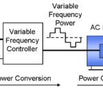
Variable frequency drives convert AC input voltage to DC, and then back to pulse-width-modulated AC voltage with variable frequency. These AC voltage pulses are controlled by insulated gate bipolar transistors (IGBTs). IGBTs have a fast switching time (also referred to as “rise time” or “dv/dt”—rate of change of voltage over time), which reduces energy losses and allows the drive to use a higher carrier frequency for sending output voltage pulses to the motor. But the downside of their fast switching time is that it creates parasitic, or unwanted, capacitance between the motor’s stator and rotor. This parasitic capacitance induces a voltage—referred to as “common mode voltage”—on the motor shaft.

motor fluting
When voltage accumulates on a motor shaft, it often finds the path of least resistance to ground via the motor bearings. This causes pitting on the bearing surfaces and ultimately leads to fluting of the raceways.
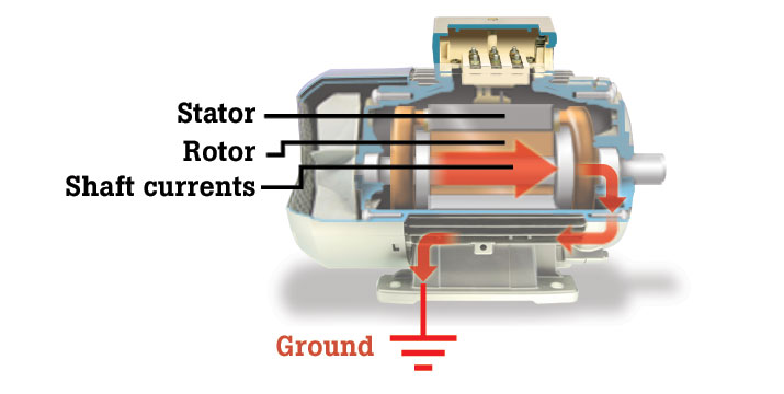
Image credit: Fluke Inc.

As this voltage accumulates on the motor shaft, the bearing lubrication acts as an insulator, but only up to a certain point. When the voltage exceeds the dielectric strength of the lubrication, it discharges through the motor bearing (i.e. the path of least resistance) to ground. The discharged current has enough energy to pit the balls and raceways of the bearing, through a process known as electric discharge machining (EDM). As these pits accumulate, they create a frosted effect and eventually result in evenly spaced grooves—much like a washboard—in the bearing raceway. This grooved pattern is referred to as fluting.


Dielectric strength is the strength of a material as an insulator. In other words, a material’s dielectric strength is the amount of voltage it can withstand before losing its insulating properties.


Motor fluting
Fluting is a type of bearing damage characterized by washboard-like ridges on the bearing raceway.
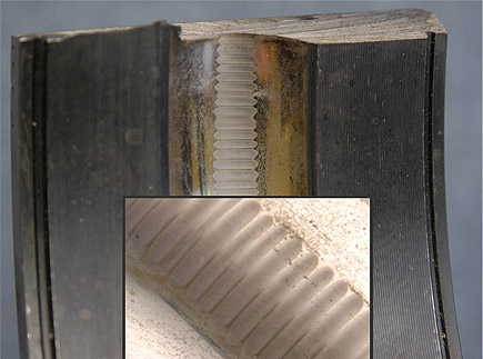
Image credit: Electro Static Technology

The first sign of bearing damage is audible noise, due to the bearing balls traveling over the pitted and frosted areas. But when noise occurs, the damage has usually become substantial enough that failure is imminent. By some accounts, electrical damage (damage caused by electric discharge machining) is the most common cause of failure for AC motors driven by VFDs.

There’s no definitive way to predict whether, or when, bearing currents will occur. But there are several methods that can be used to protect the motor bearings from fluting damage and eventual failure. These include:

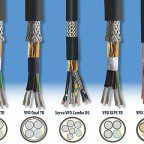
  • using shielded cables
  • grounding the motor shaft
  • using grease that conducts motor shaft currents to ground
  • using insulated bearings
  • installing a Faraday shield (conductive material between the rotor and stator)
  • installing a dv/dt filter between the drive and the motor.

You Might Also Like

Filed Under: AC Motors, FAQs + basics, Featured

Reader Interactions

Leave a Reply

You must be logged in to post a comment.

Primary Sidebar

LEARNING CENTER

Design World Learning Center

Motion Control Handbook

“mct
EXPAND YOUR KNOWLEDGE AND STAY CONNECTED
Get the latest info on technologies, tools and strategies for Design Engineering Professionals.

RSS Featured White Papers

  • Robotic Automation is Indispensable for the Logistics Industry’s Continued Growth and Success
  • Reliable Linear Motion For Packaging Machines
  • Polymers Outperform Metals In Precision Gearing

Footer

Motion Control Tips

DESIGN WORLD NETWORK

Design World Online
The Robot Report
Coupling Tips
Linear Motion Tips
Bearing Tips
Fastener Engineering.
Wire and Cable Tips

MOTION CONTROL TIPS

Subscribe to our newsletter
Advertise with us
Contact us
About us

Copyright © 2025 · WTWH Media LLC and its licensors. All rights reserved.
The material on this site may not be reproduced, distributed, transmitted, cached or otherwise used, except with the prior written permission of WTWH Media.

Privacy Policy | RSS