Torque ripple—variations in torque production during shaft revolution—is an undesirable effect that occurs in permanent magnet motors, preventing smooth motor rotation.
Torque ripple is generally defined as non-linear torque production of an energized motor. Cogging torque—a phenomenon similar to torque ripple—is torque produced by the attraction between the permanent magnets of the rotor and the slots of the stator in an un-energized motor.
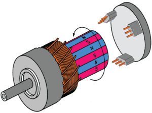
Image credit: Honeywell International, Inc.
The basic components of a BLDC motor are a rotor with permanent magnets and a stator with windings. Torque is produced by the repulsive forces between the magnetic fields of the stator and the rotor. An important distinction between BLDC motors and their counterparts, permanent magnet AC (PMAC) motors, is that the windings in a BLDC motor are trapezoidally wound, which produces a trapezoidal back EMF waveform. Because their back EMF is trapezoidal, BLDC motors typically use trapezoidal commutation, whereas PMAC motors are sinusoidally wound and use sinusoidal commutation.
In trapezoidal commutation, the rotor is monitored by three Hall sensors, which provide rotor position information every 60 degrees (rather than continuously, as with sinusoidal commutation). This produces six torque ripples per electrical cycle of the motor, or 12 torque ripples for every full mechanical revolution of the motor shaft.
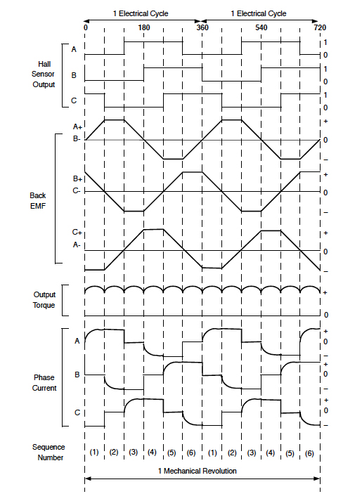
Image credit: Microchip Technology Inc.
The frequency of the torque ripple is proportional to the motor’s shaft speed. At high motor speeds, the inertia of the motor and the load can smooth out the effects of torque ripple. And at low motor speeds, high-frequency torque ripple can be filtered out using feedback and parameters in the motor controller. But if the frequency of the torque ripple is near the bandwidth of the controller’s speed loop, it can cause detrimental variations in motor speed.
The primary methods for reducing torque ripple in BLDC motors, with regard to motor design, are to increase the number of windings in the stator or to increase the number of poles in the rotor. Torque ripple can also be reduced through various control methods, taking a page from the PMAC motor playbook and using sinusoidal (rather than trapezoidal) commutation.
Although in theory the back EMF of a BLDC motor is trapezoidal, in reality, it is more sinusoidal in nature. With sinusoidal back EMF and the addition of a resolver or encoder to accurately track rotor position, it is feasible to use sinusoidal commutation for BLDC motors. And because sinusoidal commutation is continuous, torque ripple is greatly reduced.
Another commutation method, known as field oriented control (FOC), can also be used for BLDC motors. FOC provides higher efficiency and surpasses the speed limitations inherent in sinusoidal commutation, although it is more complex and can be more costly to implement.
Leave a Reply
You must be logged in to post a comment.