
Gearbox misalignment is widely recognized as the underlying cause for the majority of gearbox repairs and failures. It can degrade machine performance, reduce mean time between repair (MTBR), and decrease the operating life of the gearbox, motor, and driven equipment.
Types and causes of gearbox misalignment
Proper alignment between the shaft of a gearbox and the shaft of a motor or driven piece of equipment (such as a conveyor or actuator) means that the shafts are collinear—that is, they are positioned in a straight line. Shaft misalignment can be parallel (also referred to as “offset” misalignment) or angular. Parallel misalignment is the distance between the shafts’ axes of rotation, measured at the plane of power transmission (typically the center of the coupling), and is expressed in mils (1 mil = 0.001 inch) or mm. Angular misalignment is the difference in the slope of one shaft relative to the slope of the other shaft, expressed in mil/inch or mm/100 mm.
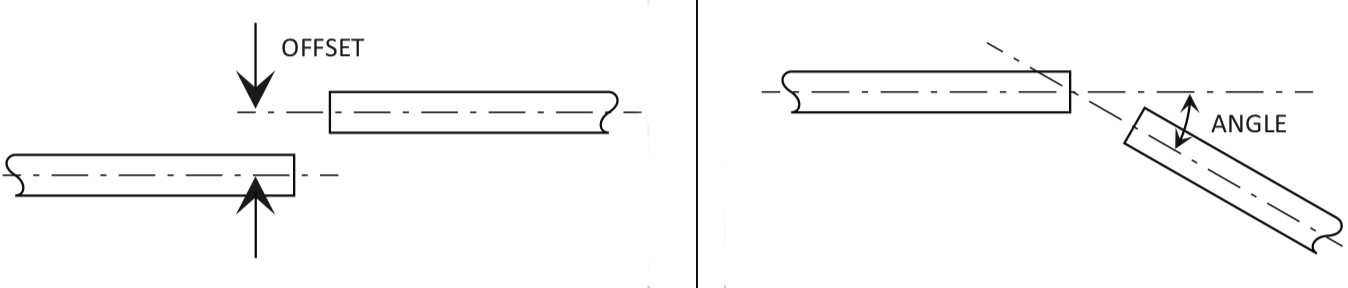
Image credit: Rexnord
Gearbox misalignment is often a result of installation and setup activities. But even if the alignment is within acceptable tolerances during installation, operating and environmental conditions can eventually cause the shafts to move out of alignment. For example, loads caused during operation and the transmission of power through the gearbox can cause shafts or other gearbox components to deflect. Thermal effects can also cause expansion or contraction of the shafts or gearbox components (especially the gearbox housing), causing the shafts to become misaligned. In extreme cases, misalignment can be so severe that bending stressing on shafts cause them to fracture and break.
The faster a shaft rotates, the smaller the acceptable misalignment value will be.
Indications of gearbox misalignment
Signs of gearbox misalignment include damage to seals or couplings, decreased bearing life, gearbox vibration, and damage to the gears themselves. If there’s significant angular misalignment, the first sign will often be seal leakage (especially for pumps and equipment with shaft seals) due to the seal being deflected by the misaligned shaft. Another result will often be excessive preload on the bearings supporting the shaft, although this may not become evident until long after the misalignment occurs. These excessive bearing loads will ultimately manifest as pitting of the races or balls and possible cage failure. Damaged bearings will eventually cause excessive vibration. Similarly, the gears themselves may also become pitted due to increased loads between the gear teeth.
Gearbox shafts are often connected to other equipment via flexible couplings, which can compensate for small amounts of misalignment, but good design practice doesn’t rely on the coupling to compensate for misalignment. Proper gearbox alignment can be achieved in some cases with dial indicators, but laser alignment tools are much more precise and less error-prone. There are no industry standards for shaft alignment tolerances, but manufacturers often specify maximum misalignment values based on testing and real-world experience.

Leave a Reply
You must be logged in to post a comment.