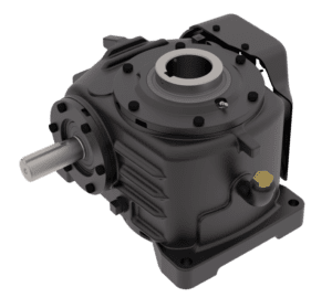
Sizing a gearbox (or gearmotor) for an industrial application typically begins with determining the appropriate service factor. In simple terms, the service factor is the ratio of the gearbox rated horsepower (or torque) to the application’s required horsepower (or torque). Service factors are defined by the American Gear Manufacturers Association (AGMA), based on the type of gearbox, the expected service duty, and the type of application.
While service factors may seem to be very specific, with thousands of combinations of gearbox types and applications each assigned its own numerical value, the criteria used to determine these values are based not on testing and empirical data, but rather on extensive review and analysis of gearbox manufacturers’ experience.
In general, the horsepower (or torque) rating of a gear tooth is based on the durability of the gear surface — its resistance to pitting — or on its bending fatigue. As the service factor of a gearbox is increased, the relationship between the gear teeth life (based on durability of the gear surface) and load is proportional to the increase in service factor, raised to the 8.78 power. In other words, if the service factor is increased by 30 percent (from 1.0 to 1.30, for example), the gear tooth life will increase 10 times (1.308.78 = 10.01).
To determine the gearbox service factor, start by consulting a set of tables or charts provided by the manufacturer, based on the type of gearing (worm, spiral bevel, helical, etc.). These tables list a wide range of applications (conveyors, cranes, winders, saws, blowers, etc.), each with (typically) three levels of service duty the gearbox is expected to see: zero to 3 hours per day; 3 to 10 hours per day; or greater than 10 hours per day. Each of these application-service duty combinations is assigned a recommended service factor.
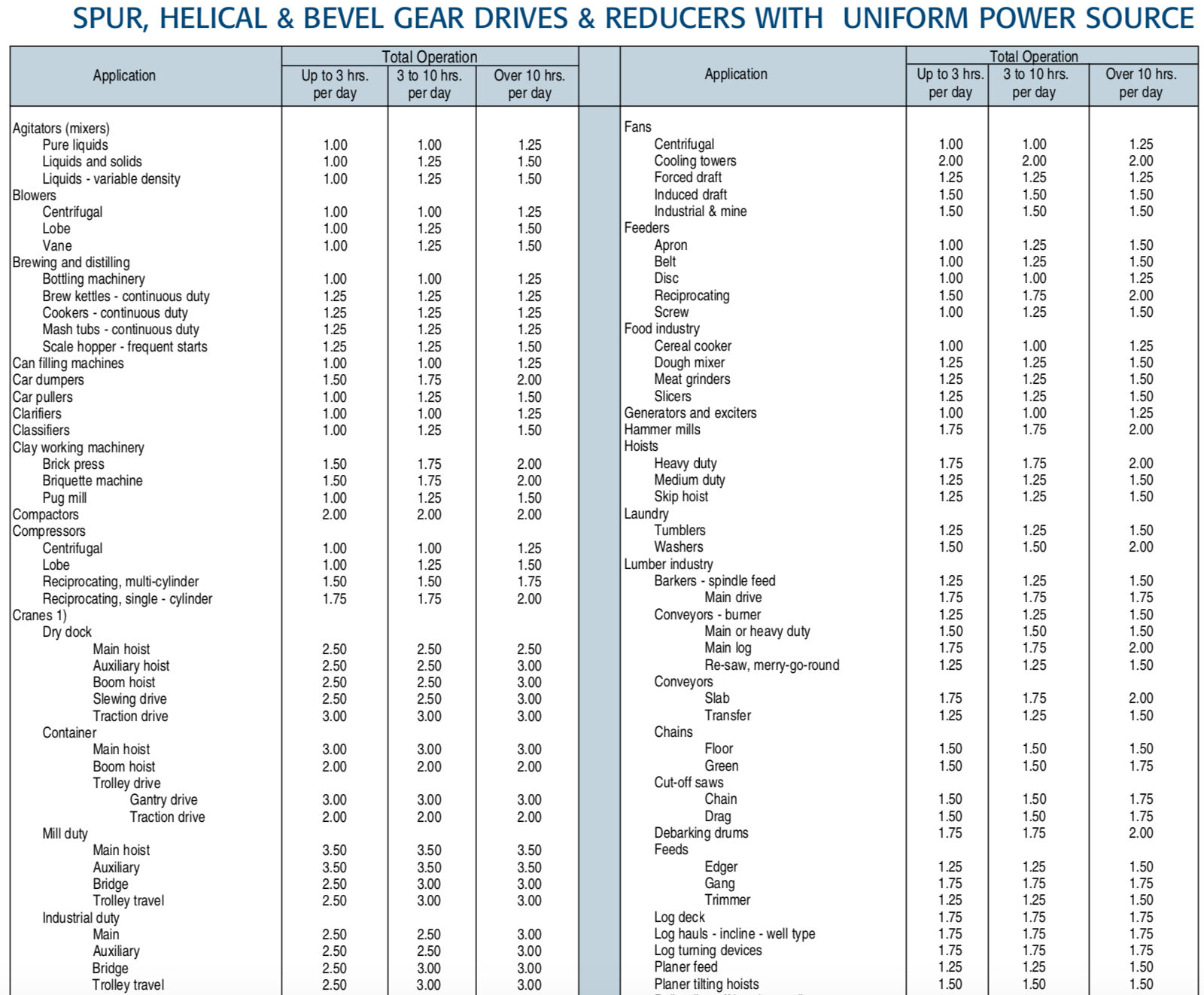
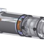
Image credit: Regal Beloit Corporation
Remember, the gearbox service factor is much like a safety factor to ensure the gearbox meets the application requirements, taking into account typical operating conditions known to exist for various types of applications. Once the AGMA-recommended service factor is determined, consider other, non-typical, working conditions that can cause additional stress and wear on the gear teeth, bearings, or lubrication. If any of these conditions exist, increase the service factor accordingly to ensure a sufficient safety margin and life of the gearbox.
Some conditions that may require an increase in the service factor are:
- Elevated temperatures
- Extreme shock loads or vibrations
- Non-uniform loads (cutting versus conveying, for example)
- Cyclic loads (frequent starts and stops)
- High peak versus continuous loads
Once the appropriate gearbox service factor is determined, multiply the service factor by the horsepower (or torque) required for the application, and the result is the output horsepower (or torque) required by the gearbox.
How does service class differ from service factor?
In some cases, manufacturers cite gearbox “service classes” rather than service factors. Service classes are designated as I, II, or III, and are generally translated to numerical service factors of 1.0, 1.4, and 2.0, respectively, to be used in gearbox sizing calculations. It’s common that even if a manufacturer publishes service classes for general application types, they also publish the more specific service factors for specific applications as well.
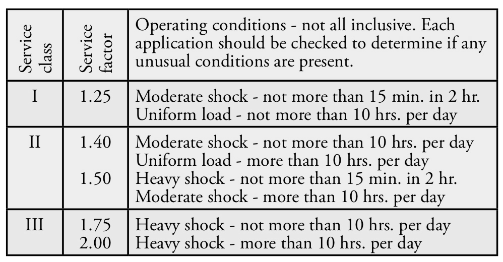
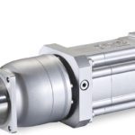
Image credit: STOBER Drives Inc.
Why don’t some catalogs list gearbox service factors?
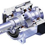
Image credit: Wittenstein
Using service factor to guide the selection of a gearbox is appropriate for applications driven by traditional AC induction motors. But because gearbox output torque, speed, and inertia are much more critical for the proper operation of a servo system, sizing a so-called “servo-rated” gearbox requires a more detailed and exact method. For gearboxes that are used in servo systems, the primary emphasis in the sizing process is on required torque and inertia match.




Leave a Reply
You must be logged in to post a comment.