Here we cover the specifics of how variable frequency drives (VFD) operate and ways to simplify their installation and setup.
 By Bob Bonczar, Yaskawa America | Technical Training Services
Variable frequency drives or VFDs — which we call simply drives in this context — operate in a wide array of industries. They’re often behind the scenes.
Nevertheless, drives impart a cost-effective and reliable level of sophistication to motor-driven applications, so deserve careful consideration and installation. Here are six tasks for OEMs and other design engineers to satisfy before initial drive startup and for some operational situations.
1. Understand what a variable frequency drive (VFD) is.
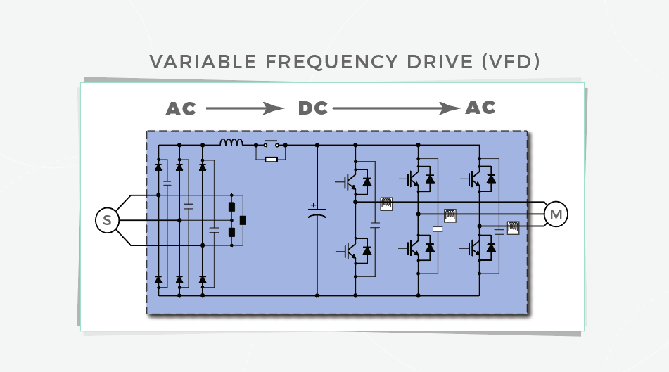
A drive is an electric and electronic device that controls a motor’s speed by changing its frequency. Applications in which drives operate vary greatly. With some changes in the wiring and programming, a drive’s purpose can change completely.
The way in which a drive changes a motor’s frequency effectively expands the usefulness of that motor, as VFD-run motors are freed from the limiting setup of only being turned on or off. The drive lets the motor quickly or slowly accelerate to reach target speed … as well as decelerate slowly or quickly.
It works like this: The drive first takes line power and converts it to direct current (dc) voltage. It then inverts it back to a simulated alternating current (ac) or pulse-width modulated (PWM) signal. The biggest benefit of drives is that they can save money by freeing the motor from needing to run at one speed all the time.
2. Understand how industrial drives are applied.
Drive applications range from pumps and fans to conveyors and extruders — and in fact are virtually limitless. Knowledge of the application at hand helps OEMs select the right drive for the job. Myriad drives exist — so the size and voltage as well as necessary options (such as the inclusion of dynamic braking or a given network interface) impact drive selection. Ultimately these variations also dictate the proper methods to setup and operate the drive.
3. Understand how the drive is expected to perform for the application.
Tip: During drive setup, develop an understanding of what’s expected from the drive and how well it must perform. Such information partially indicates what a given drive will need during setup. For example, is the drive running alone and spinning a large fan? Such an application may seem quite simple, but even here it might be necessary to interface the drive to other equipment (such as a programmable logic controller or PLC). Ask: What else is included in the system? Drives are just one piece of the design puzzle.
4. What wiring is necessary for a variable frequency drive (VFD)?
Wiring a VFD can be dangerous if the installer is unfamiliar with the product, so have a qualified electrician help or execute the entire the install.
Of course when the connections are complete, power is applied to the drive. During this step, wear personal protective equipment (or PPE including gloves, a jacket, and eye protection) to avoid injury.
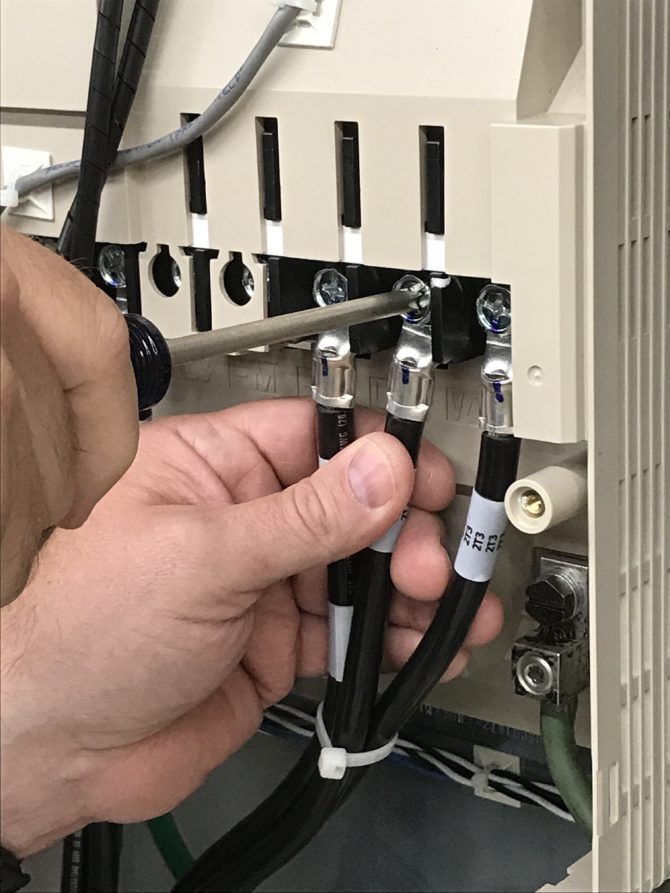
Another tip: Be sure to correctly read motor and drive schematics so that line power is connected to the correct drive terminals … and the power-output terminals are properly connected to the motor. Otherwise, there’s a risk of damage to the drive or individual harm.
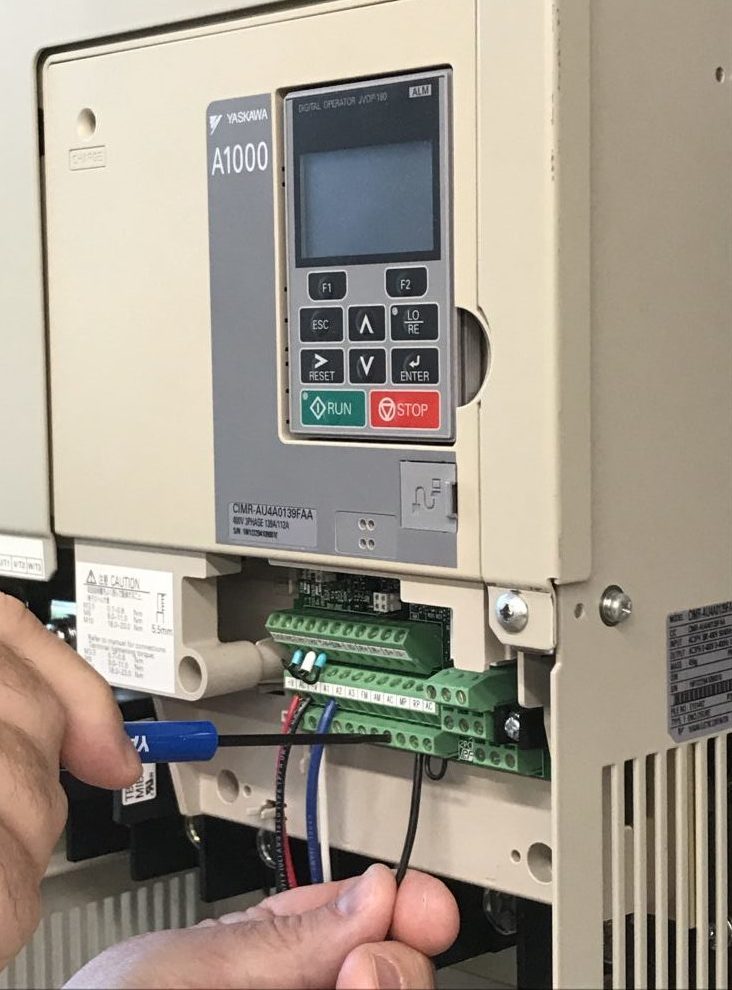
Besides wiring for power, drives require another set of wiring — the control wiring. It’s through these connections that controls will tell the drive when to start and stop — along with how fast it needs to run. Here, account for how the drive is being controlled.
If it’s being run and monitored over a network, have full understanding of how the network option installs and how to initialize it. Case in point: If using Ethernet, the PLC or computer system with which the drive interfaces also needs parameter setting for communications with the drive. Doing this correctly may necessitate contacting a system specialist during drive setup.
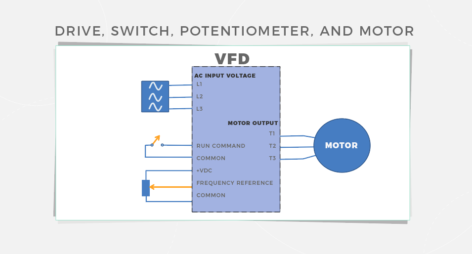
Consider one simple example of a machine design that incorporates a VFD using a start-stop switch input and an analog reference. Study of the control schematic will indicate where the connections are and how they’re designated. As in an exercise common in children’s magazines, the goal is to connect items on the left of the page to like items on the right. So in the case of VFD setup, the connections are made with shielded wiring: Items on the left are the switch and potentiometer, and the items on the right are the drive terminals.
5. What drive programming is necessary?
Until this point, drive setup is dominated by physical-installation considerations and manual connections. But drives are intelligent devices that need programming — much like new smartphones or even archaic VCRs of yore. A list of parameters must be set for the drive to understand control signals and how to respond to them. As mentioned, there are various ways to control an industrial drive — including via a network interface such as Ethernet or through switches and potentiometers.
Drives have parameters to which the end user must program the design … as drives operate to satisfy commands based on fixed system settings and inputs and outputs. The following are the minimum parameters to be set:
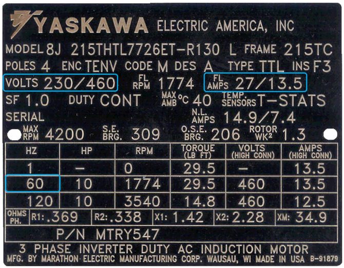
Motor name plate data:
Full load amps (FLA) • Voltage • Maximum frequency (or speed in RPM to calculate the frequency in Hz)
Control:
Run source (start and stop) • Frequency or speed reference source
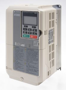
Consider one example: Using a Yaskawa 1000 series drive, these settings are …
• b1-01 frequency reference source (defaulted for terminals) • b1-02 run source (defaulted for terminals) • E1-04 maximum output frequency • E1-05 maximum output voltage • E2-01 motor FLA
In this example, the switch and potentiometer connect to the drive’s control terminals. The switch starts and stops the drive and the potentiometer adjusts the speed. Sometimes drives come defaulted to this type of interface so end users can easily install and start the drive with minimum effort.
6. Is there anything else?
Keep in mind that you may have to do some VFD troubleshooting. Once the drive is connected and networked, does the motor rotate in the correct direction? If not, then a couple of the drive output leads may need to be swapped — but not the input. This is because the input line power isn’t directly connected to the output.
Is there an alarm or fault showing? The display on the drive may show a message that indicates if there’s a condition preventing the drive from running. For example, this might be an overload condition. Here, the load to which the motor is connected will need inspection. Is it too heavy or accelerating too fast? This might necessitate physical adjustment or tuning of a parameter to start it more slowly.
In fact, other displays such as monitors can show activity such as current to help end users ensure that the drive is running optimally.
Is the drive’s output drawing excessive current? Or maybe a digital input closure isn’t taking effect. If so, the input will need monitoring for changes. A drive that stops or faults will need continuous monitoring so that it doesn’t stop again and spur more problems.
There are other considerations. What if a drive in service failed and needs replacing? Addressing this issue is a simple matter of getting an exact replacement and reprogramming it. Recent parameters will need resetting to get the drive back to the condition it’s meant to operate. For this, follow the guidelines on programming during setup.
One warning to close: If drive selection and installation are new and unfamiliar, contact a local vendor for support. Drive installation and setup can be dangerous if done incorrectly, so it’s always best to involve a designer or installer qualified to execute the process.
Yaskawa America | yaskawa.com/support-training
Leave a Reply
You must be logged in to post a comment.