
The most common use for encoders is to measure angular or linear distance, but encoders can also be used to perform speed or velocity measurements. This is possible because there is a linear relationship between an encoder’s pulse frequency and its rotational velocity. In other words, as the encoder rotates faster, the pulse frequency increases at the same rate. Encoder speed can be determined by either of two methods: pulse counting or pulse timing.
Refresher on quadrature encoding
Incremental encoders often output signals on two channels – typically termed “A” and “B” – offset by 90 degrees (in quadrature). The direction of rotation can be determined by which channel is leading. Generally, if channel A is leading, the direction is taken to be clockwise, and if channel B is leading, the direction is counterclockwise.
Quadrature output also allows the encoder’s resolution to be increased, by using X2 or X4 decoding techniques. With X2 decoding, both the rising and falling edges of channel A are counted, doubling the number of pulses counted for each rotation, and therefore doubling the encoder’s resolution. With X4 decoding, the rising and falling edges of both channels A and B are counted, increasing the resolution by four times.
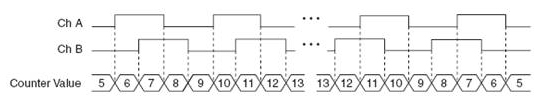
Image credit: National Instruments Corporation
Pulse counting
Pulse counting uses a sampling period (t) and the number of pulses (n) that are counted over the sampling period to determine the average time for one pulse (t/n). Knowing the number of pulses per revolution (N) for the encoder, the speed can be calculated.
ω = 2πn/Nt
Where:
ω = angular speed (rad/s)
n = number of pulses
t = sampling period (s)
N = pulses per rotation
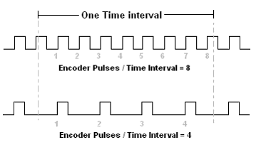
At low speeds, the resolution of pulse counting is poor, so this method is best applied in high speed applications.
Pulse timing
With the pulse timing method, a high-frequency clock signal is counted during one encoder period (the pitch, or interval between two adjacent lines or windows). The number of cycles of the clock signal (m), divided by the clock frequency (f), gives the time for the encoder period (the time for the encoder to rotate through one pitch). If the encoder PPR is denoted by N, the angular speed of the encoder is given by:
ω = 2πf/Nm
Where:
ω = angular speed (rad/s)
f = clock frequency (Hz)
m = number of clock cycles
N = pulses per rotation
At high speeds, there may be too little time between pulses for pulse timing (also referred to as pulse frequency) to accurately measure clock cycles, so this method is best for low speed applications.
Accuracy of speed measurement
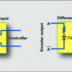
The accuracy of the encoder speed measurement can be affected by a variety of factors, including instrument errors, quantization errors, and interpolation errors. Instrument errors include both mechanical imperfections in the encoder and errors in the pattern on the code disc or reticle, such as variations in spacing between lines or windows. Also included in instrument-related errors are substrate flatness, inexact positioning of sensors, and lack of concentricity between the encoder and the shaft.
Quantization error stems from the fact that there is no information between pulses or readings. In other words, quadrature encoders only read the edges of the signals on one or both channels (A and B), and relay no information between these readings. Quantization error is inherently ± ½ of the measuring step, or count.
Interpolation error occurs only if the encoder resolution is increased electronically beyond the X4 decoding that is inherent to quadrature encoders. Interpolation error tends to increase with increasing encoder speed. Both interpolation and quantization errors can be reduced by using encoders with higher line counts or a greater number of windows.


Leave a Reply
You must be logged in to post a comment.