
Rotating equipment such as motors, gearboxes, and fans can experience a torque overload if the system encounters an unexpected malfunction such as a jam or crash of the driven load. One way to protect these expensive components — and to avoid physical injury to personnel — is to install a torque limiter in the drive train.
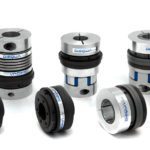
A torque limiter is a device that immediately decouples, or isolates, the driving equipment from the driven equipment when a torque overload occurs. Torque limiters come in several designs and methods of operation, including ball detent, shear pin, permanent magnet, and sprag engagement types.
In this article, we’ll take an in-depth look at ball detent torque limiters.
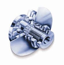
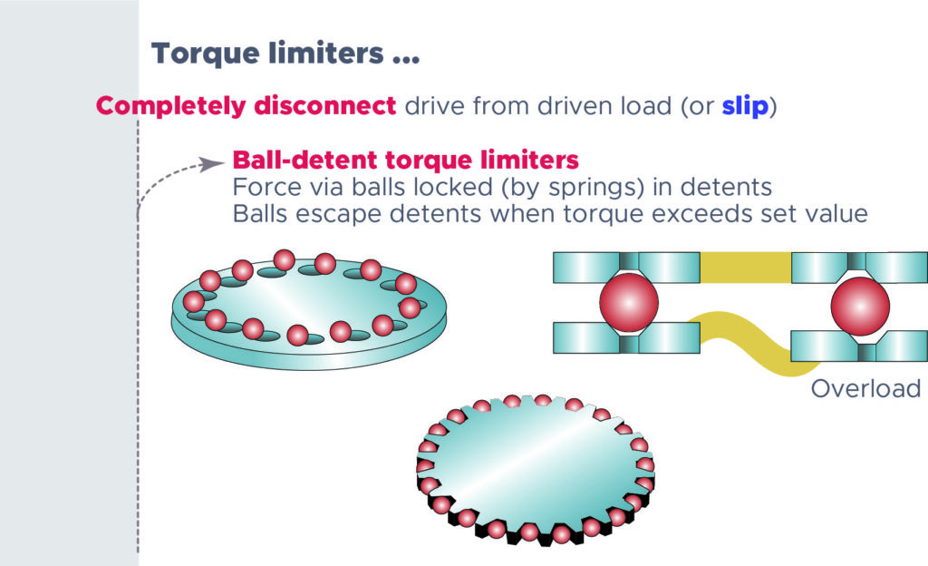
Ball detent torque limiters are relatively simple devices, relying primarily on balls or rollers and springs for their operation. But despite this simplicity, they provide fast, reliable, and highly accurate and repeatable response to torque overloads. Here’s how they work:
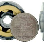
Balls or rollers sit in detents between two plates or flanges. The assembly is forced together — and the balls are held in their detents — by a spring force, usually via disc springs. The entire assembly rotates as one unit… unless there’s a torque overload. When an overload occurs — that is, when the torque exceeds a preset limit — the spring force is overcome, and the balls roll out of their detents, disconnecting the driving and driven components.
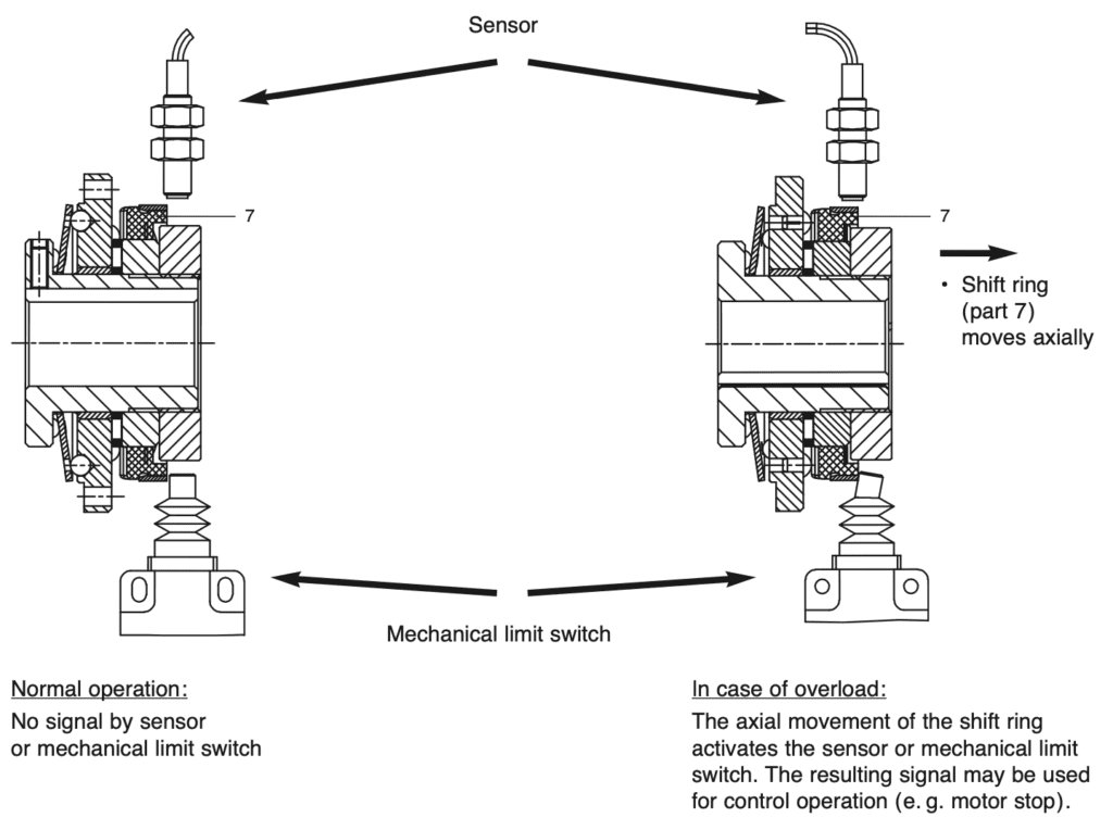
In many torque limiter designs, a plate on the non-driven side moves axially to trigger a mechanical switch or proximity sensor, which is used to alert the operator and/or remove power from the drive to stop the motor.
Re-engagement of the torque limiter can occur in one of two ways, depending on whether the restart should happen as quickly as possible, regardless of the relative positions of the driving and driven loads, or whether the driving and driven load should remain synchronized upon restart.
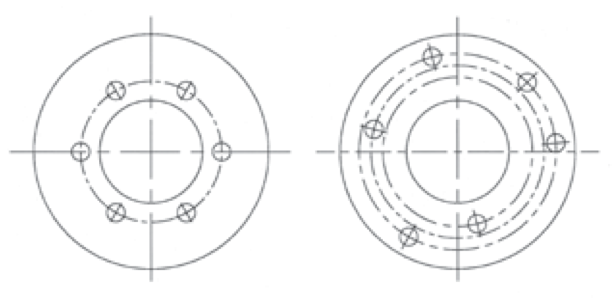
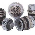
Image credit: Rexnord
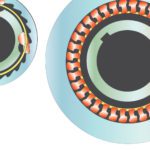
If the restart should happen as quickly as possible, and synchronization of the driving and driven loads is not important, the detents are equally spaced around the plate, or flange. After the balls have rolled out of their detents and the overload condition is removed, each ball will fall into the next detent, automatically resetting the device. This design is sometimes referred to as a “random” or “multi-position” reset torque limiter. It’s important to note that with this design, the torque limiter will continue to “trip,” or ratchet, until the overload condition is corrected, which can cause significant wear on the plates and detents.
In applications where synchronization of the driving and driven load should be maintained, the detents are arranged in an asymmetric, or scattered, pattern. Once the overload condition is remedied, the balls will only re-engage when the plates (and, therefore, the driving and driven load) return to their original relative positions. This design is often referred to as a “synchronous” or “single-position” reset design.
Although commonly referred to as “torque-limiting clutches” or “overload clutches,” at least one industry expert contends that torque limiters aren’t technically clutches, because they’re not meant to be continuously slipped.
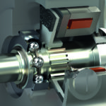
Ball detent torque limiters are common on servo-driven axes such as machine tools, woodworking equipment, robots, and packaging machines. Although servo systems often incorporate electronic torque overload protection, ball detent torque limiters can react much faster — typically within a few milliseconds — to minimize the potential for damage that high-inertia loads can cause.
To see the various styles of torque limiters in action, check out this compilation of torque limiter videos.
Leave a Reply
You must be logged in to post a comment.