
The load-to-motor inertia ratio is a critical parameter in servo motor sizing and performance. As we discussed in a previous article, one of the most significant effects of using a gearbox in a servo system is its ability to help optimize the inertia ratio.
Why inertia ratio is important
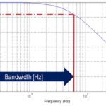
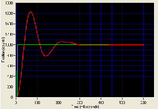
If the motor inertia is too low relative to the load inertia, the load will essentially try to “drive” the motor, causing overshoot and resonance. In order to effectively control the load, the motor will need to draw higher current than should be necessary, which decreases efficiency and increases operating costs.
On the other hand, if the motor inertia is too high relative to the load inertia, the motor is oversized, meaning that it was more costly than necessary and uses more energy than needed for the application.
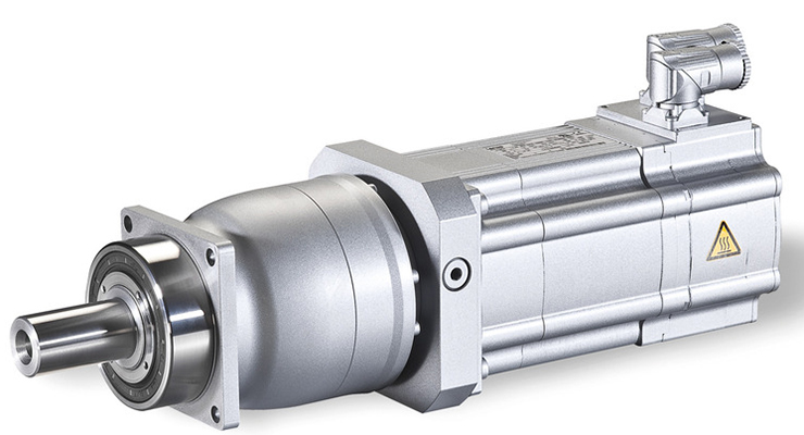
Image credit: Lenze
A perfect inertia ratio of 1:1 is often impractical and, in many applications, unachievable. And most applications operate well with an inertia ratio of 5:1, 10:1, or even 100:1 or higher in some cases. The “best” inertia ratio depends on a variety of application-specific factors, including the system dynamics (acceleration and deceleration), the required positioning accuracy, and the amount of overshoot and settling time that can be tolerated.
The rule of thumb goal for inertia matching, recommended by most servo sizing guidelines, is 10:1 or less. But in reality, the “best” inertia ratio is specific to each application, and may be lower than 10:1 for applications with high dynamics and high precision requirements, or much higher than 10:1 for applications with high feedback resolution and fast response times to rapidly correct errors and avoid instability.
How the gear ratio affects the inertia ratio
The inertia ratio is simply the load inertia divided by the motor inertia.
![]()
JL = inertia of load reflected to motor
JM = inertia of motor
The motor inertia is provided by the motor manufacturer, and the load inertia includes all components that the motor must move: belt & pulley or screw drive system, attached load, and coupling.
![]()
JD = inertia of drive (screw, belt & pulley, or actuator)
JE = inertia of external (moved) mass
JC = inertia of coupling
When a gearbox is added, the inertia of the load is reduced by the square of the gear ratio:
![]()
i = gear ratio
![]() Note that the inertia of the gearbox is added to the load inertia, as shown to the right.
Note that the inertia of the gearbox is added to the load inertia, as shown to the right.
However, gearbox inertia typically contributes only a small amount to the overall load inertia. And, we haven’t chosen a gearbox yet, so we’re disregarding gearbox inertia for this exercise.
If the desired inertia ratio is known, the necessary gear ratio can be found by rearranging the inertia ratio equation, using the reduced load inertia (JL/i2), to get:
![]()
For example, if the desired inertia ratio, Jratio, is 5:1, with a motor inertia, JM, of 0.1 kgcm2, and a load inertia, JL, of 20 kgcm2, the required gear ratio is:
![]()
So we should choose a gearbox with reduction of 6:1 or similar in order to achieve a 5:1 inertia ratio between the load and the motor.
The key to optimizing the performance of a servo system is to find the right combination of components (motor, servo amplifier, mechanical drive mechanism, feedback) and operating parameters (inertia ratio, gains and tuning values, move profile) that provides the desired performance with the highest possible efficiency. And the most efficient combination includes a motor with the lowest inertia that can produce maximum acceleration without causing the system to become unstable, produce too much overshoot, or fall short of accuracy requirements.


Leave a Reply
You must be logged in to post a comment.