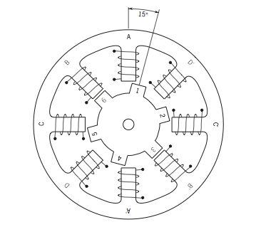
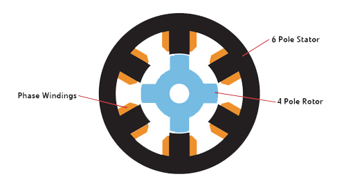
Switched reluctance motors operate by switching currents in the stator windings in response to changes in the magnetic circuit formed by the rotor and stator. The stator of a switched reluctance motor contains windings, similar to a brushless DC motor, but the rotor is simply made of steel that is shaped into salient poles, with no windings or magnets. To avoid a situation where all the poles of the rotor and the stator line up simultaneously (and no torque is produced), switched reluctance motors have fewer poles on the rotor than on the stator.

Image credit: scienceprog.com
When the rotor and stator poles are out of alignment, the magnetic circuit between them has a high reluctance. As the stator pole pairs are energized, the rotor turns to align with the energized stator poles, which minimizes the reluctance of the magnetic circuit. This tendency of the rotor to move to a point of minimum reluctance produces what is referred to as reluctance torque.
Energizing of the stator poles must be precisely timed to ensure that it occurs as the rotor pole is approaching alignment with the energized stator pole. Unlike stepper motors, which can, and for most purposes do, operate in open-loop mode, switched reluctance motors require position feedback from an encoder or Hall effect sensors, to control commutation of the stator currents based on the precise rotor position.
This article provides an in-depth look at drive options for switched reluctance motors, and this article looks at how drive technologies could make switched reluctance motors more common in the future.

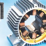
Image credit: chargedevs.com
Switched reluctance motors have fewer poles and a larger stepping angle than stepper motors. While stepper motors are typically chosen for positioning applications, where step integrity and high resolution are important, switched reluctance motors are used in applications where power density is a primary concern.
Because switched reluctance motors have rotors with no magnets or windings, they have lower inertia and can therefore achieve higher accelerations and speeds than motors with permanent magnet rotors, such as stepper motors. The lack of magnets on the rotor provides other benefits as well – including the ability to withstand higher temperatures (less cooling required) and simple, lower-cost construction than permanent magnet motors.
Another difference between switched reluctance motors and stepper motors lies in the stator construction. In a switched reluctance motor, there is no overlap of coils between successive phases – in other words, the phases are independent of one another. This means that if one or more phases fail, the motor will still be operable, although with reduced torque output.
The fact that both the stator and rotor have salient poles (referred to as a doubly salient design) means switched reluctance motors produce more audible noise than stepper motors. The primary source of noise is distortion of the stator due to radial forces that occur when the stator pole pairs are energized. The energized pole pairs are attracted to one another, causing radial forces strong enough to distort the stator.
Salient poles are simply magnetic poles that essentially “stick out” from the diameter of the rotor (or stator), towards the stator (or rotor).
Torque ripple is also a common issue with switched reluctance motors. While both switched reluctant and stepper motors exhibit torque ripple, this effect is minimized in stepper motors with a higher number of phases (5 phases versus 2, for example). In a switched reluctance motor, torque ripple can be reduced by using a higher number of poles in both the rotor and the stator, but this decreases the motor’s average torque output, requiring a tradeoff between torque production and acceptable torque ripple.


Leave a Reply
You must be logged in to post a comment.