In the article What are functional safety standards for servo drives? we review how functional safety is quantified. Now consider one example of a spring-set pneumatically released friction servomotor brake now having a third-party safety rating (from Intertek Group) certifying compliance with international safety standard ISO 13849-1.
Intertek is an international London-headquartered inspection, assurance, product testing, and certification organization that issues functional safety standards to industrial products. Testing on these components is executed at more than 1,000 Intertek laboratories and offices across the globe. Spring-set power-off brake excel at locking servomotor-driven loads (and providing unbeatably safe holding) without consuming electrical power or exhibiting torque fade — plus provide far more safety assurance than holding a load with the servomotor … which can also overheat if required to hold an axis stationary too long.
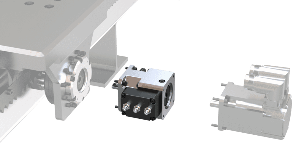
The new servomotor brake mechanically attaches to the servomotor via an integrated clamp collar with keyways that serve as a backup in the unlikely event that the clamp collar fails. The brake most commonly installs between the motor and a gearbox … and customized inputs and outputs are possible to complement the design’s exact configuration. When installed in the recommended configuration, the brake is Intertek-certified to operate at a functional-safety Category Level up to 4 and Performance Level up to e.
Safety-certified brakes adherent to standard ISO 13849-1 have a cycle life (B10D) of two million cycles and a common cause failure (CCF) of 75% — indicating a reliably predicable failure mode. Mission time (defined by ISO 13849-1 as the time between complete replacement or refurbishment) is 10 Years. Mean time to dangerous failure (MTTFD) is 100 years assuming the above B10D along with a H(op) value of 16 hours/day, a D(op) value of 260 days per year, and a maximum cycle rate of 74.8 seconds per cycle.
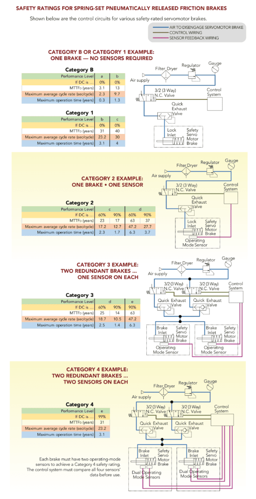
| Category B | ||||
| Performance Level | a | b | ||
| If DC is … | 0% | 0% | ||
| MTTFD (years) | 3.1 | 13 | ||
| Maximum average cycle rate (sec/cycle) | 2.3 | 9.7 | ||
| Maximum operation time (years) | 0.3 | 1.3 | ||
| Category 1 | ||||
| Performance Level | b | c | ||
| If DC is … | 0% | 0% | ||
| MTTFD (years) | 31 | 40 | ||
| Maximum average cycle rate (sec/cycle) | 23.2 | 30 | ||
| Maximum operation time (years) | 3.1 | 4 | ||
| Category 2 | ||||
| Performance Level | c | d | ||
| If DC is … | 60% | 90% | 60% | 90% |
| MTTFD (years) | 23 | 17 | 63 | 37 |
| Maximum average cycle rate (sec/cycle) | 17.2 | 12.7 | 47.2 | 27.7 |
| Maximum operation time (years) | 2.3 | 1.7 | 6.3 | 3.7 |
| Category 3 | ||||
| Performance Level | d | e | ||
| If DC is … | 60% | 90% | 90% | |
| MTTFD (years) | 25 | 14 | 63 | |
| Maximum average cycle rate (sec/cycle) | 18.7 | 10.5 | 47.2 | |
| Maximum operation time (years) | 2.5 | 1.4 | 6.3 | |
| Category 4 | ||||
| Performance Level | e | |||
| If DC is … | 99% | |||
| MTTFD (years) | 31 | |||
| Maximum average cycle rate (sec/cycle) | 23.2 | |||
| Maximum operation time (years) | 3.1 | |||
Diagnostic coverage (DC) depends on the level of brake redundancy along with its sensor setup. If DC is 0% no sensor feedback necessary. If DC is 60% then a feedback sensor will be required to monitor the brake’s operating mode. If DC is 90% then a feedback sensor will be required to monitor the brake’s operating mode of brake … and the brake must be cycled (engaged and disengaged) at least every three months to check for brake functionality. If DC is 99% the same applies and the brake must be cycled once every day to check for brake functionality.
Brake features to help achieve these levels of functional safety include:
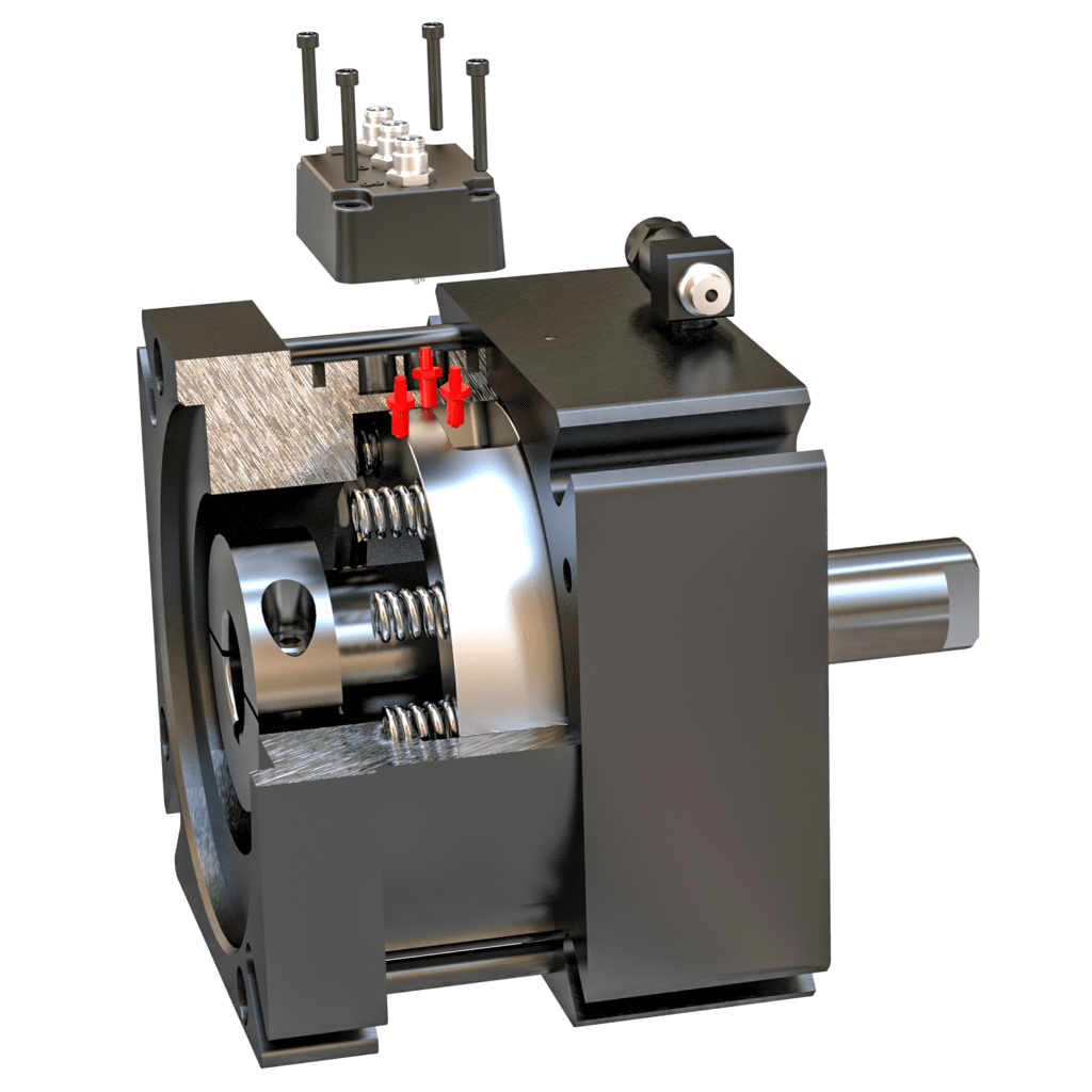
1. Multiple engagement springs that default to lock.
2. Friction surfaces with a proprietary frustoconical friction facing — tapered on both the inner and outer friction surfaces. (Frustoconical indicates a truncated cone shape.) Those surfaces apply the braking (locking) force via springs concurrently to both the rotating shaft and brake housing to hold the shaft from rotating … all with zero backlash.
3. Up to three operating-mode sensors for feedback to ensure safe emergency stopping and holding. These are essentially inductive proximity sensors to sense three different brake conditions:
• Disengagement: This proximity sensor in the brake activates when rated air pressure enters the brake’s the piston circuit to essentially pull the friction-facing pair apart — for a disengaged (free-running motor torque) axis condition.
• Engagement: This proximity sensor in the brake activates when the piston and facing friction-surface pair move into engagement and application of braking (stopping) torque.
• Wear: This proximity sensor in the brake activates when the brake is engaged but the friction facing is worn enough to necessitate replacement.
Nexen Group | www.nexengroup.com
Leave a Reply
You must be logged in to post a comment.