In this four-part article series, we cover the fundamentals and new innovations related to EtherCAT. (Read the previous installment here.) In this installment, we detail how EtherCAT detects errors with cyclic redundancy checks, frame check sequences, and working counters; how EtherCAT subdevice controllers take the place of standard Ethernet switches and MAC and IP addressing; and how the application layers of Modbus TCP, EtherNet/IP, PROFINET, and EtherCAT compare. We close with the IEC and ISO standards and the EtherCAT Technology Group or ETG that govern the protocol.
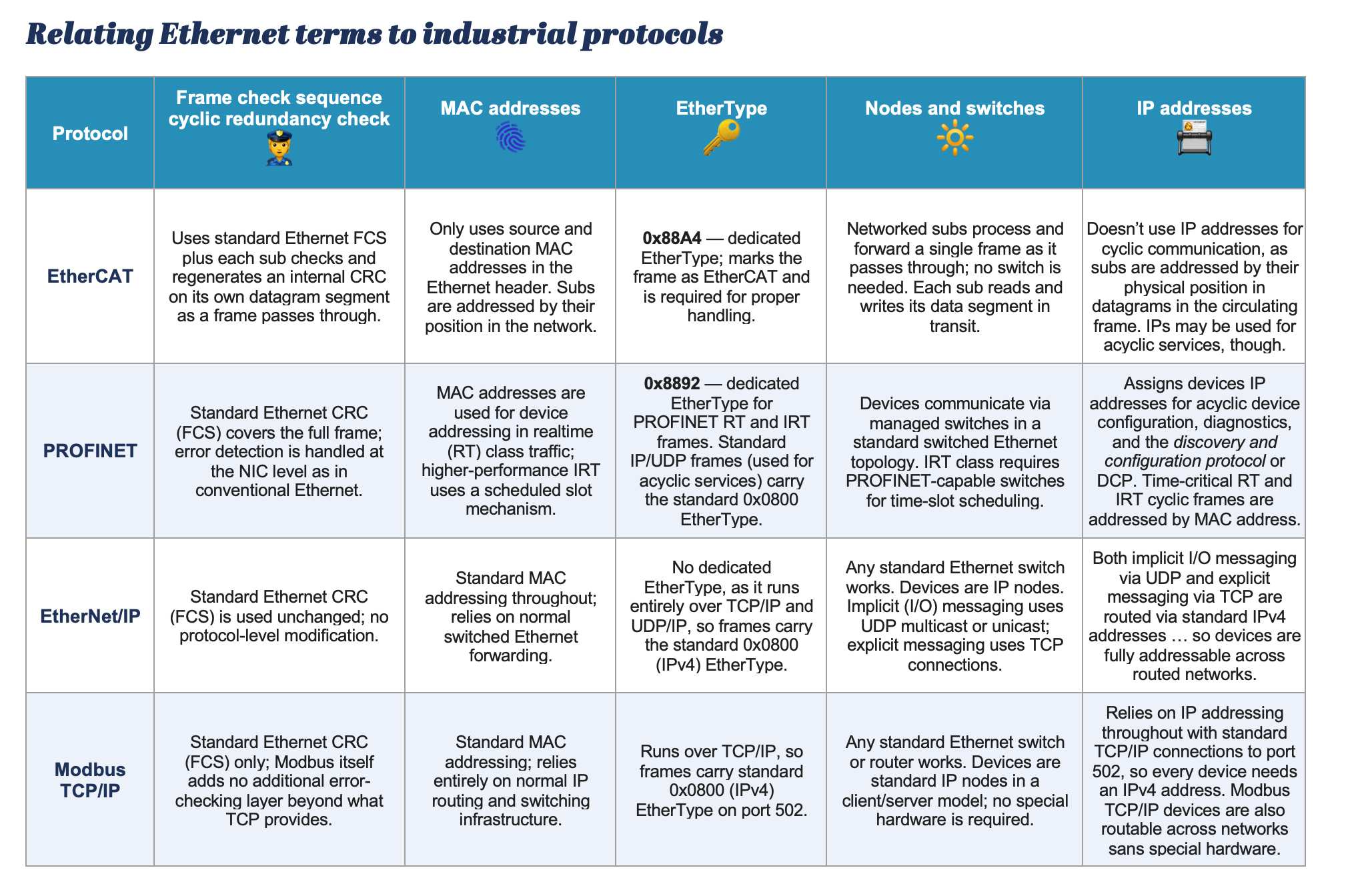
Cyclic redundancy checks or CRCs are the mathematical algorithm used to detect errors in data transmission yielding a frame check sequence or FCS — a 4-byte field at the end of a frame that carries the CRC result. The FCS on the outer Ethernet frame is separate and independent check covering the entire frame. Any frames that fail CRC are just dropped.
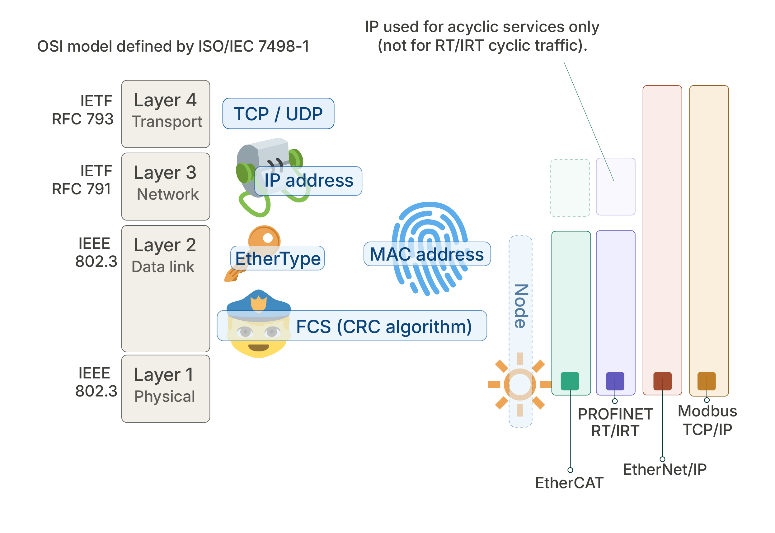
With EtherCAT, every subdevice effectively checks the frame in both directions. A subdevice detecting an error modifies the FCS so downstream subdevices recognize it’s already flagged … and that way, the main device can easily pinpoint the erroring network segment.
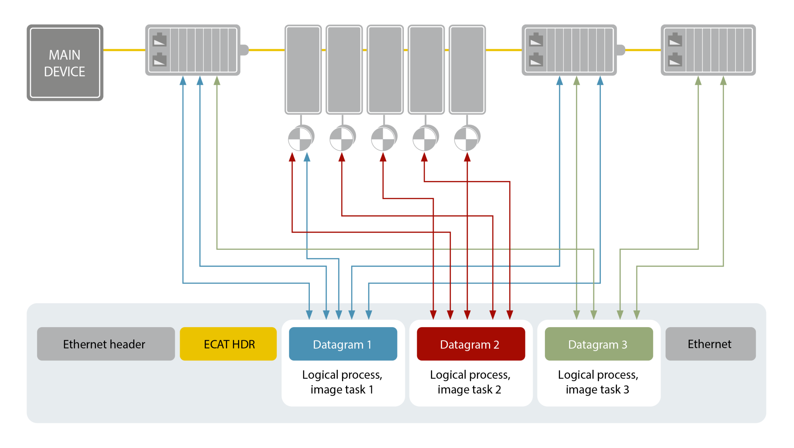
In fact, EtherCAT makes a second integrity check. Every EtherCAT subdevice proofs and regenerates verification on its own datagram embedded within the circulating frame’s payload. The working counter or WKC is a 16-bit integer appended to each datagram — not the Ethernet frame itself. Every sub that successfully employs a command increments the WKC so read and write operations each add one and a read-write adds three. Then the EtherCAT main compares the WKC it gets back against what’s expected. Any mismatch indicates at least one sub in the logical process image didn’t participate as expected due to being unreachable, in the wrong state, or encountering some error.
Both this check (and subs parsing frame content) and the FCS happen on the data link for sophisticated per-hop error detection on Layer 2 without IP involvement.
Ethernet switching in industrial protocols
Most industrial-Ethernet protocols rely on switches — networking hardware with multiple ports to allow communication between devices in the local area network (LAN). So, we’re still in the domain of IEEE … and 802.1 defines how switches decide where to send data.
Many office and industrial networking arrangements include unmanaged Ethernet switches (bridges) that operate at Layer 2. These read the destination MAC address in each arriving frame, consult an address table, and forward the frame out to the correct port. Managed switches can execute this plus (in many cases) routing at Layer 3 for forwarding decisions based on IP addresses — and segment a network into virtual LANs or VLANs.
In EtherCAT, except for connections to enterprise-level systems, there are no standard switches … and each EtherCAT device has an internal processing ASIC called an EtherCAT subcontroller or ESC with forwarding logic. Then two or more Ethernet ports (RJ45, M8, or fiber) allow connection to the previous node and next node in the network.
This makes for a self-terminating network, as any node not detecting a “next node” automatically becomes the terminus … and “boomerangs” the data-transmit stream back as a data-receive stream. Hence EtherCAT networks can be wired in star, line, tree, or ring topologies.
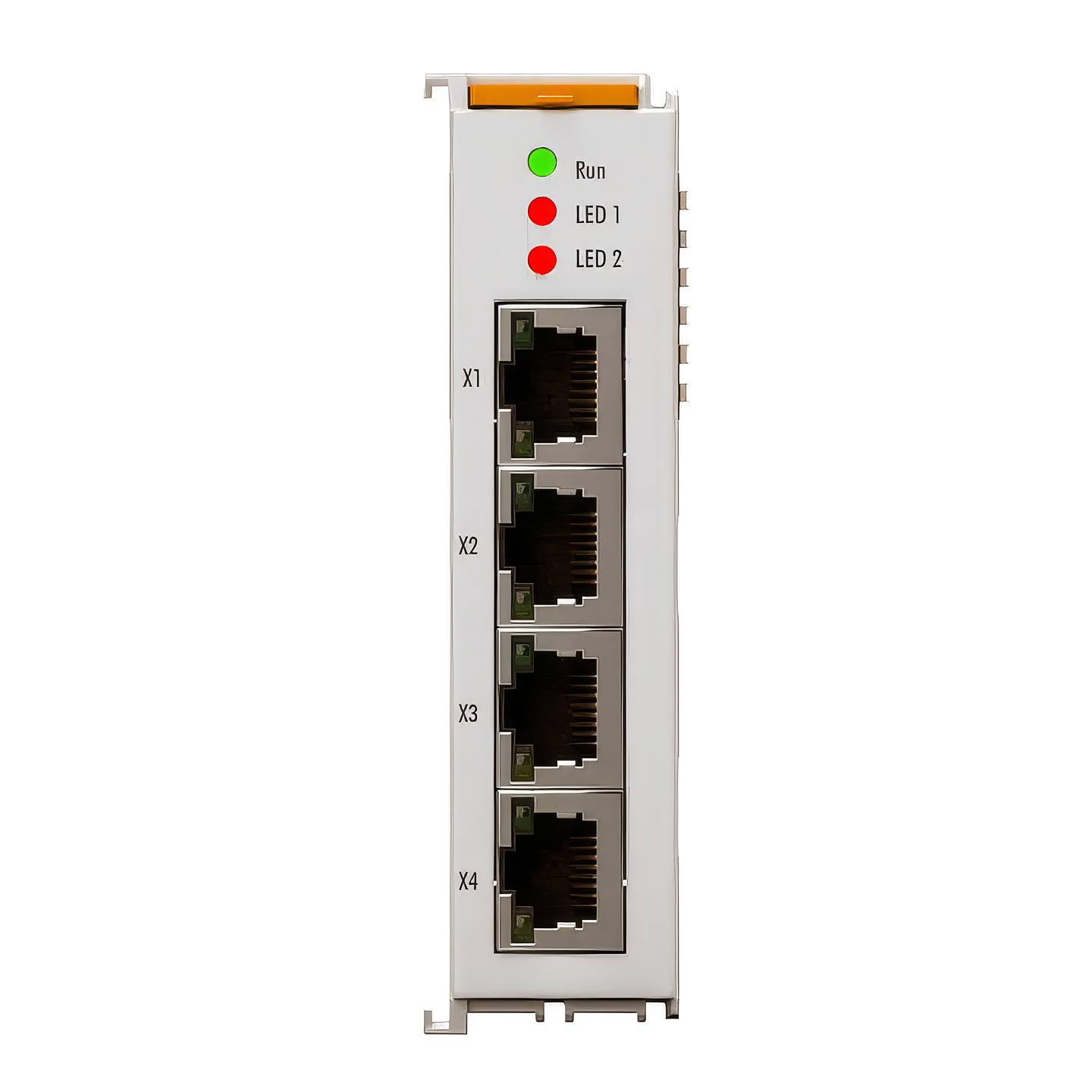
Consider what’s possible with EtherCAT microcontroller units or MCUs that forward frames on-the-fly without any switching logic — in contrast with PROFINET IRT and even EtherNet/IP Device Level Ring MCUs that need to embed an actual switch chip in each node.
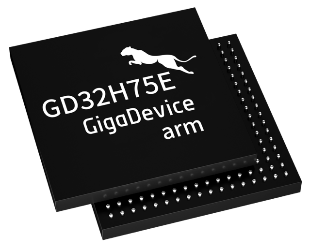
Some EtherCAT MCU chip makers are imparting their products with more Ethernet physical layer transceiver or PHY connectivity to bridge the physical layer (electrical signals) and digital layer (the digital signals they become) sans any separate FPGA or ASIC (such as Beckhoff’s ET1100). The GigaDevice chip is an integrated EtherCAT subdevice controller with two built-in Ethernet PHYs for use in servomotor applications such as humanoid robotics (to give one example).
Besides the flexibility in topology, EtherCAT also avoids the delays and timing issues of certain store-and-forward switch communication that must receive and verify (via the FCS) frames before forwarding them onward. What’s more, EtherCAT systems don’t need installers to buy, wire, configure, and maintain dedicated switches or Ethernet devices with this circuitry.
MAC and IP (Layer 3) addresses in industrial protocols
PROFINET and EtherNet/IP use frame MAC addresses for local delivery and IP addresses for network delivery. In the case of EtherNet/IP, MAC and IP addresses handle underlying Ethernet frame delivery and device identification for Common Industrial Protocol (CIP) on the application layer on top of standard TCP/IP or UDP/IP. CIP defines a standardized object model and messaging services for configuring, controlling, and collecting data from industrial devices such as drives, sensors, and I/O modules, making it the common language that EtherNet/IP uses to move automation data across a network.
In contrast, EtherCAT eschews use of MAC and IP addresses at the fieldbus level. Instead, the main device assigns addresses using hardware logic called fieldbus memory management units or FMMUs on each networked subdevice for positional addressing (upon startup), configured-station addressing (during initialization), logical addressing (for normal operation), and broadcast addressing (primarily for synchronized resets).
In this way, EtherCAT avoids trojan and virus malware exposure via IP at its subdevices so can be handled like a fieldbus instead of IT infrastructure. The main must be protected, but an EtherCAT main is typically a PC running Windows or Linux much like those running the most critical infrastructure today … including cloud, banking, and government systems. So, engineers can secure EtherCAT main devices with the same tools and methods used to secure Windows or Linux servers: Put it on a domain, use Active Directory, apply normal IT security policies with familiar patching and hardening strategies.
Layer 7: The application layer in industrial protocols
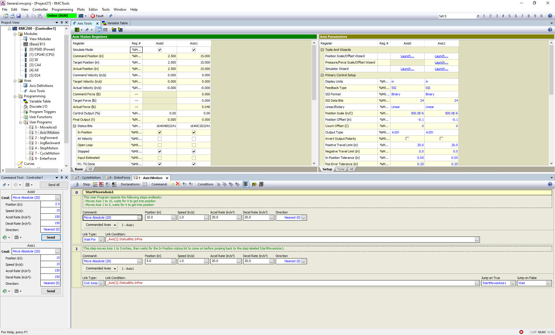
Sitting atop Ethernet layers, the application layer defines how devices name, structure, exchange, and assign meaning to data.
Consider one end of the spectrum: Modbus TCP, all data appears as coils or 16-bit registers with no cross-vendor standardization. Because the client (main) must poll each device individually, a message may carry only a single register value — for example, the status of a valve controller — so many Ethernet frames are heavy on protocol overhead rather than payload.
EtherNet/IP builds on CIP to organize data into an object, instance, and attribute hierarchy with support for event handlers and state machines. That structure is richer than Modbus, but the poll-based request-response dynamic can still mean low payload.
PROFINET IO mirrors the rack, slot, channel, and point addressing model of PROFIBUS, providing a familiar structure for engineers transitioning from legacy fieldbus systems. PROFINET IO supports cyclic data exchange, so process data is transmitted at regular intervals without polling. That makes more efficient use of available bandwidth than other protocols.
As mentioned earlier, EtherCAT is most efficient in how it maps every subdevice to a segment of a shared process data image. This accommodates communication profiles such as:
- CAN application protocol over EtherCAT (CoE)
- Servodrive profile according to IEC 61800-7-204 (SoE)
- Ethernet over EtherCAT (EoE)
- File access over EtherCAT (FoE)
- ADS over EtherCAT (AoE)
Functional Safety over EtherCAT or FSoE is also accommodated though this uses a black channel.
There’s always a tradeoff: One objection of some engineers is that EtherCAT tooling and initial configuration have a steeper learning curve than other protocols because EtherCAT maps all subdevice data into a single contiguous address space. So, each FMMU must be properly configured … necessitating the understanding of process-image construction before any data is exchanged. Some software tools abstract that configuration but other software (including open-source Simple Open EM) exposes this complexity.
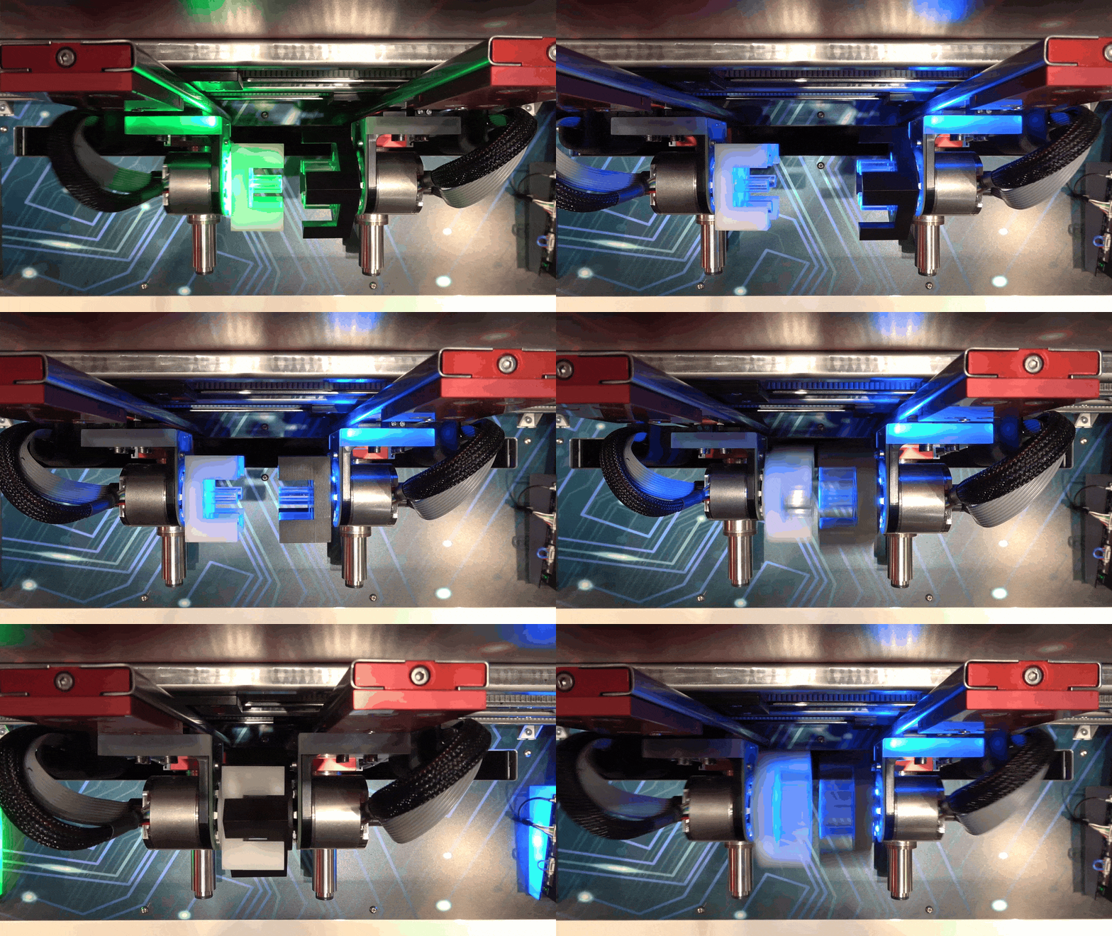
EtherCAT allows more than 65,000 nodes per segment so there’s no practical limit for machine networks. That said, EtherCAT can make sense even for modest designs with just a few axes and a handful of I/O points. A main only needs a standard Ethernet port (with no special interface card) and the subcontroller chips are inexpensive.
Governing standards, supplier proliferation, and the ETG

EtherCAT was made an open protocol in 2003 — when the EtherCAT Technology Group (ETG) was founded. Today, the standard reflects the input of component suppliers and end users as well as that from experts across roughly 20 communication systems and industry-specific variants.
What’s more, the ETG works with the International Electrotechnical Commission (IEC) for standardization. Today, EtherCAT is integrated into IEC fieldbus standards 61158 and 61784-2 as well as ISO 15745-4. In addition, widespread support by the semiconductor industry has made it simple and cost effective for suppliers (especially for motion control) to embed EtherCAT directly into drives, motors, sensors, and I/O components.

Leave a Reply
You must be logged in to post a comment.