• Skip to primary navigation
  • Skip to main content
  • Skip to primary sidebar
  • Skip to footer
  • Advertise
  • Subscribe

Motion Control Tips

Automation • Motion Control • Power Transmission

  • News
    • Industry News
    • Editor Blogs
  • Controls
    • HMIs
    • PC-Based Controllers
    • PLCs + PACs
    • Stand-Alone Controllers
    • Software
  • Drives
    • Servo Drives
    • Stepper Drives
  • Encoders
    • Absolute Encoders
    • Incremental Encoders
    • Rotary Encoders
  • Mechanical
    • Bearings
    • Brakes + Clutches
    • Belt + chain
    • Couplings
    • Gears + Gearing
    • Lubrication
    • Shock + Vibration Mitigation
    • Springs + Rings + Seals
  • Linear
    • Actuators
    • Linear Motors
    • Linear Encoders
  • Motors
    • AC Motors
    • DC Motors
    • Brushless Motors
    • Gearmotors
    • Piezo Motors
    • Servo Motors
    • Stepper Motors
  • Systems
    • Conveyors + linear transport systems
    • Gantries + Stages
    • Rotary Tables
    • Grippers + End Effectors
    • Robotics
  • Networks
    • Connections + Sliprings
    • Fieldbuses
    • I/O
    • Sensors + Vision
  • Resources
    • FAQs
      • Motion Casebook
      • Motion Selection Guides
    • Suppliers
    • Video
You are here: Home / FAQs + basics / The Torque Equation and the Relationship with DC Motors

The Torque Equation and the Relationship with DC Motors

March 9, 2017 By Danielle Collins Leave a Comment

Understanding the torque equation and the relationship between speed and torque is an important part of selecting and operating a DC motor.

DC motors are relatively simple machines: when the load on the motor is constant, speed is proportional to supply voltage. And when supply voltage is constant, speed is inversely proportional to the load on the motor. This second relationship—between speed and load (or torque)—is typically shown on the motor’s torque-speed curve.

torque equation
Image credit: National Instruments Corporation

The inverse relationship between speed and torque means that an increase in the load (torque) on the motor will cause a decrease in speed. This can be demonstrated by the DC motor torque equation:

torque equation 1

Where:

T = motor torque

V = supply voltage

ω = rotational speed

k = motor constant

R = resistance

Of course, the motor constant (k) doesn’t change, and resistance (R) in the motor windings is constant. Therefore, when supply voltage (V) is constant, torque (T) is inversely proportional to speed (ω).

Rearranging for speed, we can see the same inverse relationship to torque:

torque equation


To see the derivation of the DC motor torque equation, check out this article.


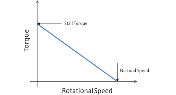
The inverse relationship means that the torque-speed curve is a descending line, with a negative slope. The torque-speed curve begins at the crossing of the Y axis, where torque is maximum and speed is zero. This is the stall torque—the maximum torque when the motor is running at nominal voltage. The curve slopes downward until it intersects the X axis—that is, zero torque and maximum speed. This point is known as the no-load speed—the speed when running at nominal voltage and zero load.

Because the torque-speed curve is a straight line, it’s simple to find the torque that the motor can produce at a given speed, or conversely, to find the motor’s speed for a given load (torque) on the shaft. Recall the equation for a straight line:

torque equation speed

Where:

y = value of y axis variable, to be determined

m = slope of the line; change in y divided by change in x

x = value of x axis variable, given

b = y intercept; point at which the line crosses the y axis

Using this equation for the torque-speed curve, we can find the motor’s torque at a given speed. In this case, the variables in the line equation represent the following:

y = torque to be determined

m = change in torque divided by change in speed

x = given speed

b = stall torque (value where the line crosses the y axis)

The line equation can also be rearranged to find the motor’s speed at a given torque:

torque equation


You Might Also Like

Filed Under: DC Motors, FAQs + basics, Featured

Reader Interactions

Leave a Reply

You must be logged in to post a comment.

Primary Sidebar

LEARNING CENTER

Design World Learning Center

Motion Control Handbook

“mct
EXPAND YOUR KNOWLEDGE AND STAY CONNECTED
Get the latest info on technologies, tools and strategies for Design Engineering Professionals.

RSS Featured White Papers

  • Robotic Automation is Indispensable for the Logistics Industry’s Continued Growth and Success
  • Reliable Linear Motion For Packaging Machines
  • Polymers Outperform Metals In Precision Gearing

Footer

Motion Control Tips

DESIGN WORLD NETWORK

Design World Online
The Robot Report
Coupling Tips
Linear Motion Tips
Bearing Tips
Fastener Engineering.
Wire and Cable Tips

MOTION CONTROL TIPS

Subscribe to our newsletter
Advertise with us
Contact us
About us

Copyright © 2025 · WTWH Media LLC and its licensors. All rights reserved.
The material on this site may not be reproduced, distributed, transmitted, cached or otherwise used, except with the prior written permission of WTWH Media.

Privacy Policy | RSS