The measure of how efficiently a piece of equipment or facility uses power to produce work is known as its power factor. Although resistive loads, such as heating and lighting, have a high power factor, inductive loads, including AC induction motors, don’t use all of their supplied power to produce useful work, so their power factors tend to be low. This distinction is especially important for industrial plants because utility providers often levy penalties and additional charges to facilities with low power factors.
Power factor is a dimensionless quantity between 0 and 1.0. A power factor that falls below 0.85 is typically considered “low” by utility companies.
AC induction motors use power for two tasks: to induce a magnetic field in the rotor, and to produce torque via power delivered to the stator. The power supplied to the stator is referred to as “real” or “active” power because it produces work, while the power used to induce the magnetic field in the rotor is referred to as “reactive” power because it does not actively produce work. Utility companies determine power factor based on real power and another measure known as “apparent power.”
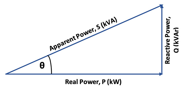
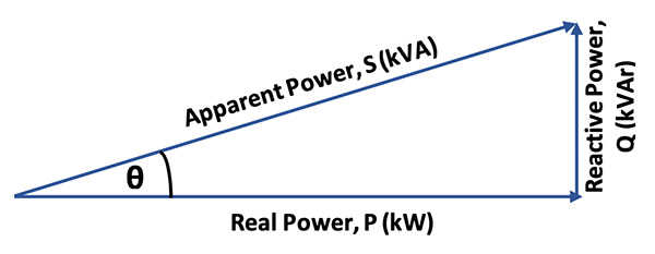
To understand apparent power, it helps to visualize it (together with real and reactive power) on a power triangle. The power triangle is a right triangle, where the real power and reactive power are at right angles to each other, and apparent power is the hypotenuse. The power factor is the cosine of the angle θ (the angle between the real and apparent power). Since the cosine is found by dividing the adjacent leg of the triangle by the hypotenuse, the power factor is the real power divided by the apparent power.
![]()
![]()
The angle θ represents the displacement, or phase difference, between the voltage and current. The reactive power required for inductive loads tends to pull current and voltage out of phase, resulting in a larger angle θ and, therefore, a lower power factor.
If there is no phase difference between voltage and current, the angle θ is zero. The cosine of zero degrees is 1 (cos(0) = 1), so the power factor is 1. On the other hand, if the voltage and current are out of phase by 90 degrees, θ equals 90. The cosine of 90 degrees is zero (cos(90) = 0), so the power factor is zero!
Although the real power consumed by an AC induction motor varies with the motor’s load, the amount of reactive power the motor uses remains constant regardless of the load. You can see from the power triangle that to increase the power factor (reduce the angle θ), the reactive power needs to be reduced.
 This is where power factor correction capacitors come in — they generate reactive power and therefore reduce the amount of reactive power the motor requires from the utility. The end result is a higher power factor.
Power factor correction capacitors can be either fixed or automatically switched. Fixed power factor correction capacitors are typically installed for individual motors or banks of motors. These capacitors are on when the motor is on (and off when the motor is off), which avoids having capacitance on the system when the motor is not requiring reactive power.
Automatically switched capacitors are used in centralized capacitor banks and are often installed at the utility power entrance to the facility. These capacitors provide varying amounts of power factor correction to address the entire facility.
Another way to improve the power factor of an AC induction motor is to install a variable frequency drive (VFD). The DC bus capacitors in the VFD supply the necessary reactive power to the motor for inducing the rotor’s magnetic field, so the AC supply line only has to supply real power, meaning that all (or nearly all) the supplied power is used for useful work.
Feature image credit: Energex




Leave a Reply
You must be logged in to post a comment.