
Power factor is essentially a measure of how effectively a piece of equipment (or an entire facility) uses electricity to produce useful work, such as heating, lighting, or motion. Electricity companies monitor power factor and often charge customers a penalty if their power factor falls below a specified threshold — typically 0.90 or higher.
Fortunately, most electrical loads in residential buildings are resistive (heating and lighting, for example) and have a high power factor, so consumers aren’t normally subjected to this metric. Industrial plants, on the other hand, typically have high inductive loads that significantly reduce their power factor. For example, AC induction motors — which are used for driving pumps, fans, compressors, and conveyors — have relatively low power factors, even when their capacity is put to full use. And when these motors are lightly loaded, their power factor drops even lower — sometimes approaching zero.
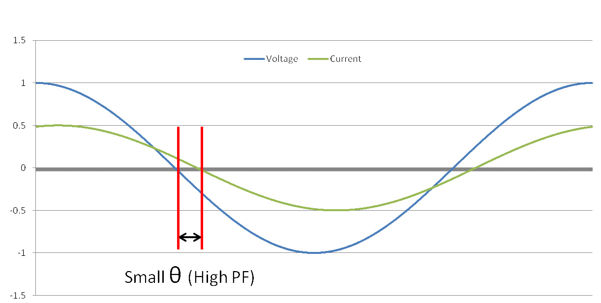
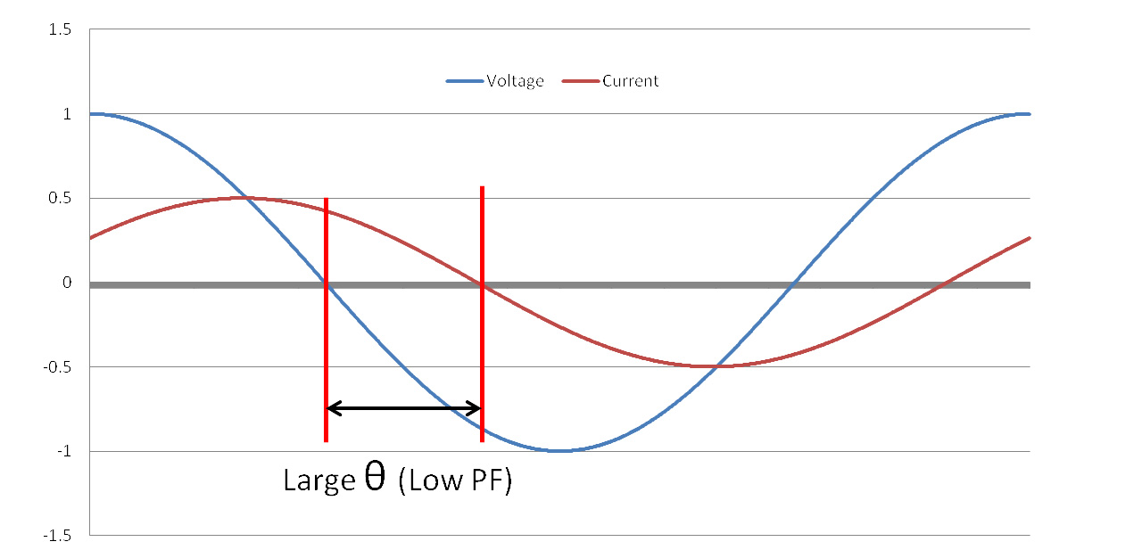
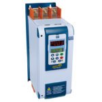
Image credit: Yaskawa America
There are several methods of improving power factor in an industrial facility, but when the main culprits are induction motors — especially induction motors not operating at full load — applying variable frequency drives (VFDs) is often the best solution.
Recall that in an AC induction motor, power is supplied directly to the stator and a magnetic field is induced in the rotor. The power supplied to the stator is referred to as “real,” or “active” power because it produces torque. The power used to induce the magnetic field in the rotor is referred to as “reactive” power because it does not actively produce work. The combination of real power and reactive power is referred to as “apparent” power. Real, reactive, and apparent power are often depicted on a power triangle.
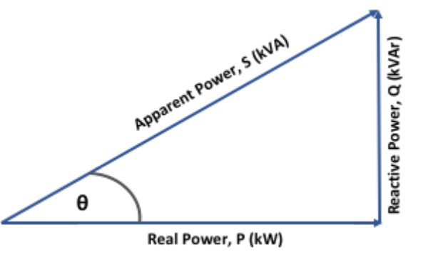
In an ideal system, power factor (PFD) is the cosine of θ, which equals real power (P) divided by apparent power (S).
![]()
![]()
Note the subscript, D, in the power factor notation. In the power triangle, θ represents the displacement (phase difference) between voltage and current. Thus, this expression of power factor is often referred to specifically as the displacement power factor, PFD.
For resistive loads, all (or nearly all) of the power used is real power that produces useful work — heat or light, for example. Therefore, current and voltage remain in phase (θ = 0), and the power factor is near unity (i.e., 1). But the reactive power required for inductive loads — to induce a magnetic field in a rotor, for example — tends to pull the current out of phase with the voltage (hence, a larger θ angle), causing a lower power factor.
The amount of real power required by an induction motor varies with the load, but the amount of reactive power (power required to generate the rotor’s magnetic field) is constant regardless of the load. Thus, when an induction motor is lightly loaded, the ratio of real power to apparent power decreases, resulting in a lower power factor.
Using VFDs to drive induction motors can improve power factor — but it’s not the panacea that some manufacturers suggest.
Variable frequency drives typically have very high PFD values. This is because the DC bus capacitors supply the necessary reactive current to the motor for inducing the rotor’s magnetic field, and the AC supply line only has to supply real power. This means voltage and current remain almost perfectly in phase, with very little displacement, and the power factor can be at or near unity.
But VFDs also introduce harmonic current distortion. And because harmonic currents don’t produce useful work, they are reactive, thus negating some of the power factor benefits of the VFD.
To determine the true power factor, PFT, which includes the effect of harmonic distortions, we use the equation:
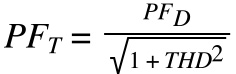
THD = total harmonic current distortion
Fortunately, there are ways to reduce this VFD-induced harmonic distortion and minimize its effects on power factor. For VFDs that use a standard, diode-based rectifier, adding impedance via a line reactor or DC link choke will reduce THD.
Another option is to use an active front end (AFE) drive, which is a VFD that uses IGBTs, rather than diodes, to rectify the incoming AC power to DC. Active front end drives have significantly lower THD than standard diode-based rectifier designs. For example, an AFE drive typically has THD around 5 percent, where a standard VFD with a diode-based rectifier can have THD in the range of 45 percent.
Q: Why does the utility care how efficiently a plant or equipment uses the power it supplies?
A: Because low power factor causes higher line currents, which put more stress (primarily in the form of heat) on cables, transformers, and other equipment. Also, the lower the power factor, the more apparent power (kVA) the utility must supply to meet the real power (kW) requirements.

Leave a Reply
You must be logged in to post a comment.