
Many of the components that make up a variable frequency drive (VFD) are semiconductor components, which are sensitive to power or current surges, voltage spikes, line distortion, and general power anomalies. A line reactor is an optional component that can be added to a drive system to protect the VFD and other devices from power surges and transients.
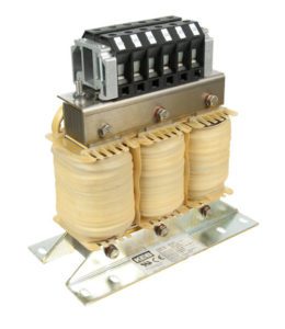
A line reactor is essentially an inductor—a coil of wire that forms a magnetic field as current flows through it. The magnetic field limits the rate of rise of the current, which reduces harmonics and helps avoid unnecessary tripping of the drive.
A reactor can be referred to as either a line reactor or a load reactor, depending on where it’s installed. A line reactor (also called an input reactor) is installed before the VFD and protects the drive, while a load reactor (also called an output reactor) is installed after the VFD and protects the motor.
When a current wave form is not sinusoidal, it’s said to contain harmonics. Harmonic distortion (often referred to as THID, or total harmonic current distortion) can be as much as 85 percent for a three-phase rectifier using six diodes or thyristors and a filter. A line reactor lowers the current peak and extends the wave further over time, making it more sinusoidal. This lowers the harmonic level to around 30 to 35 percent and improves system performance and reliability.
The basic equation for an inductor is:
V = L (di/dt)
Where:
V = voltage (volts)
L = inductance value of the reactor (Henries)
di/dt = rate of change of current (amps/s)
This equation shows that an increase in current will cause voltage to be induced. But this induced voltage has the opposite polarity of the applied voltage, so it reduces the rate of rise of current.
The inductance value also influences the inductor’s reactance, whose equation is:
XL = 2πFL
Where:
XL = inductive reactance (ohms)
F = applied frequency of AC source (Hz)
L = inductance value of reactor (Henries)
So the reactor adds impedance to the AC circuit in proportion to both its inductance value and the applied frequency.
Line reactor vs load reactor
Line reactors stabilize, or smooth, the current waveform, which reduces over voltage (or under voltage) line tripping and potential damage to the drive. They also protect the drive under motor short-circuit conditions by slowing the rate of rise of the current. This gives time for protection circuits in the drive to react safely, preventing damage to components such as transistors. Line reactors also reduce the burden on upstream electrical components.
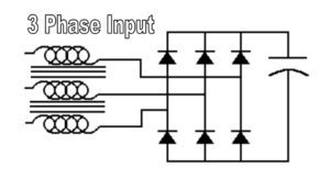
Image credit: Rockwell Automation
Load reactors are used primarily when the distance between the VFD and the motor is very long, generally 100 feet or more (although the distance depends on the motor). VFDs tend to produce noise spikes, which are amplified by long cable lengths and the additional capacitance of the cables. Load reactors can protect the motor from damage by preventing these spikes. They also dampen the dv/dt (rate of change of voltage) that is applied to the motor windings, which improves performance of the motor and of the system.
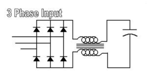
Image credit: Rockwell Automation
Percent impedance: 3% or 5%
Line (and load) reactors are classified by their percent impedance (denoted as percent IZ or %IZ), which is the voltage drop due to impedance, at the rated current, expressed as a percent of rated voltage. The most common line reactors have either 3 or 5 percent impedance. Reactors with 3 percent impedance are sufficient for most solid-state applications in North America. They absorb normal line spikes and motor current surges and can prevent most nuisance line tripping of circuit protection devices.
When higher line disturbances are present, 5 percent impedance reactors may be needed. If an application is installed in a location outside North America, or if IEEE 519 compliance is required, a higher impedance reactor is generally recommended. If the aim is to diminish noise from the motor or to extend motor life, higher impedance reactors can be used to reduce harmonics even further. This additional performance typically comes at a higher cost than 3 percent impedance versions. But, when multiple motors are controlled by a single drive, a single load reactor can placed between the VFD and the motors, simplifying the system layout and reducing cost.
Feature image credit: Rockwell Automation

Leave a Reply
You must be logged in to post a comment.