
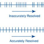
As an encoder detects a change in magnetism (for magnetic encoders) or light (for optical encoders), it produces two analog sinusoidal voltages, phase-shifted by 90 degrees. These analog signals are interpolated (divided into smaller increments by the encoder electronics) to increase the encoder’s resolution and then converted to digital output signals.
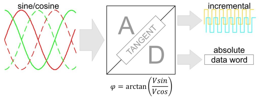
Image credit: iC-Haus GmbH
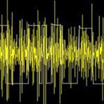
If there are errors in the original sinusoidal signals — due to the encoder read head, measuring scale (for linear encoders), or disc (for rotary encoders) — the quality of the interpolation will be degraded and the encoder’s accuracy will be reduced.
Errors caused by the encoder read head can be analyzed by plotting the encoder’s sine and cosine signals on a Lissajous figure (also referred to as a Lissajous curve).
Encoder read head errors are often referred to as sub-divisional errors or cyclic errors, because they occur with each signal period.
Image credit: wikipedia.com
To create Lissajous figures, the magnitudes of the signals are plotted over time, with the sine wave on the Y axis and the cosine wave on the X axis. For sinusoidal signals shifted by 90 degrees (referred to as quadrature signals), the resulting Lissajous figure should form a perfect circle, centered at the 0,0 position, with the size of the circle corresponding to the amplitude of the signals.
Deviations in the size of the circle indicate gain error, while deviations in the position of Lissajous figures (not centered at 0,0) indicate offset error. Both gain and offset errors can be caused by the signal conditioning process within the encoder electronics. If the figure is elliptical rather than circular, this indicates phase error, in which the sine and cosine signals are not shifted by exactly 90 degrees. Phase error is caused by quantization — the process of converting from a continuous, analog sine/cosine signal to a discrete, digital signal.
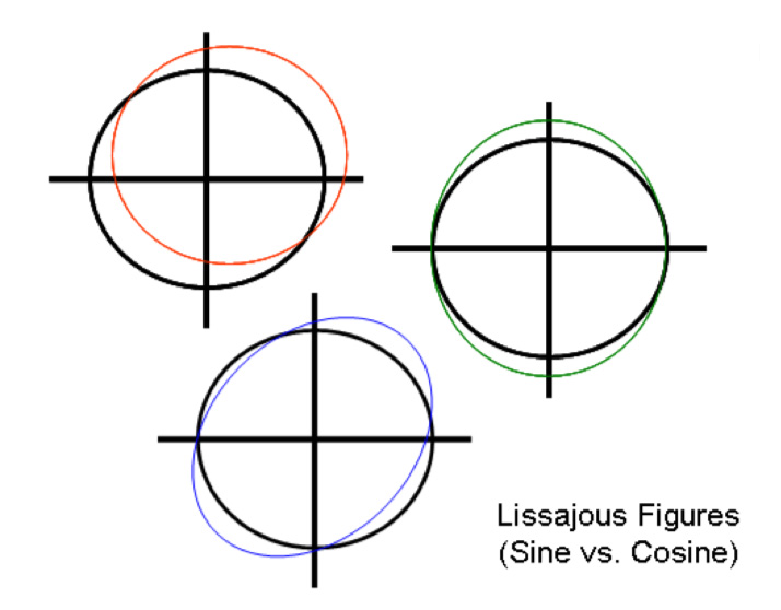
Image credit: Celera Motion
The process of interpolation involves dividing the circular Lissajous figure into smaller segments and using these segments to create the square wave digital output (or binary word). If the Lissajous figure is not a perfect circle, the spacing of the square wave edges will be inaccurate and result in erroneous position readings. Encoder electronics sometimes include gain, offset, and phase correction mechanisms to reduce the effects of sub-divisional errors.
Sub-divisional errors are independent of the measuring range and do not accumulate, but they can be problematic for systems that require very tight position or speed control — especially direct drives such as linear motors. This is because linear motors typically use a single encoder to provide both position and speed information, with speed being derived from position readings.
If sub-divisional errors are not corrected, the encoder cannot provide accurate position information, and in turn, speed information will be inaccurate. Direct drives often operate with high control loop gains so they can respond quickly to errors in position or speed. But as the motor’s speed increases, so does the frequency of the error, and the controller becomes unable to respond quickly enough to keep up with the error. The controller’s attempt to keep up causes the motor to draw high current, which can cause audible noise and excessive heat in the motor.
Feature image credit: Beckhoff
Leave a Reply
You must be logged in to post a comment.