
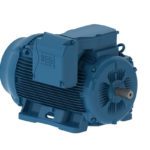
One of the most important operating parameters of motor and gearmotor operation is the temperature of the motor windings. Motor heating is caused by mechanical, electrical, and copper losses, as well as heat transferred to the motor from external sources, including the ambient temperature and surrounding equipment.
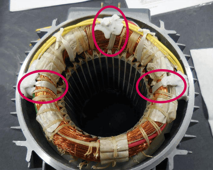
Image credit: KEB America
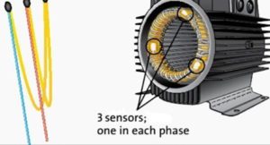
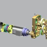
If the temperature of the motor windings surpasses the maximum rated temperature, the windings could be damaged or the motor insulation could break down or completely fail. This is why a majority of motors and gearmotors — especially those used in motion control applications — have thermistors or silicon resistive sensors (also referred to as KTY sensors) integrated into the motor windings. These sensors monitor winding temperature directly (instead of relying on measurements of current) and are used in conjunction with protective circuits to prevent damage due to excessive temperature.
PTC and NTC thermistors
Thermistors are devices that exhibit a predictable and precise change in resistance when they experience a change in temperature — regardless of whether the temperature change is caused by conduction or radiation from the surrounding environment or by self-heating due to power dissipation. Thermistors are divided into two primary types: those with a positive temperature coefficient (PTC) and those with a negative temperature coefficient (NTC). Positive temperature coefficient thermistors experience an increase in resistance as temperature rises, while negative temperature coefficient devices experience a decrease in resistance as temperature rises.
Positive temperature coefficient thermistors are typically made of ceramic material that has been doped to create a semiconductor. These semiconductor PTC sensors have a non-linear resistance-temperature curve, and at a critical temperature (sometimes referred to as the switch temperature or Curie temperature), resistance increases significantly. This sharp spike in resistance can be used to trigger protective relays that switch off current to the motor, preventing damage to the windings and insulation.
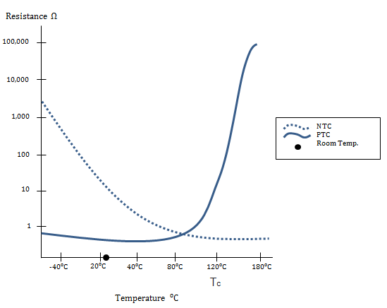
Image credit: Ametherm
Negative temperature coefficient thermistors are made from a type of ceramic (polycrystalline oxide ceramic) that exhibits a very precise change in resistance as temperature changes. Where PTC thermistors exhibit a “switching point” at a critical temperature, NTC thermistors are better suited for precise temperature monitoring over a wide temperature range and are often used for monitoring and limiting inrush current.
Silicon resistive sensors (aka KTY sensors)
Another type of positive temperature coefficient sensor is the silicon resistive sensor, also referred to as a KTY sensor (the series name given to this type of sensor by Philips, the original manufacturer of KTY sensors). These PTC sensors are made of doped silicone and manufactured with a process referred to as spreading resistance, which makes resistance nearly independent of manufacturing tolerances. Unlike PTC thermistors, which experience a sharp rise in resistance at a critical temperature, KTY sensors have a nearly linear resistance-temperature curve.
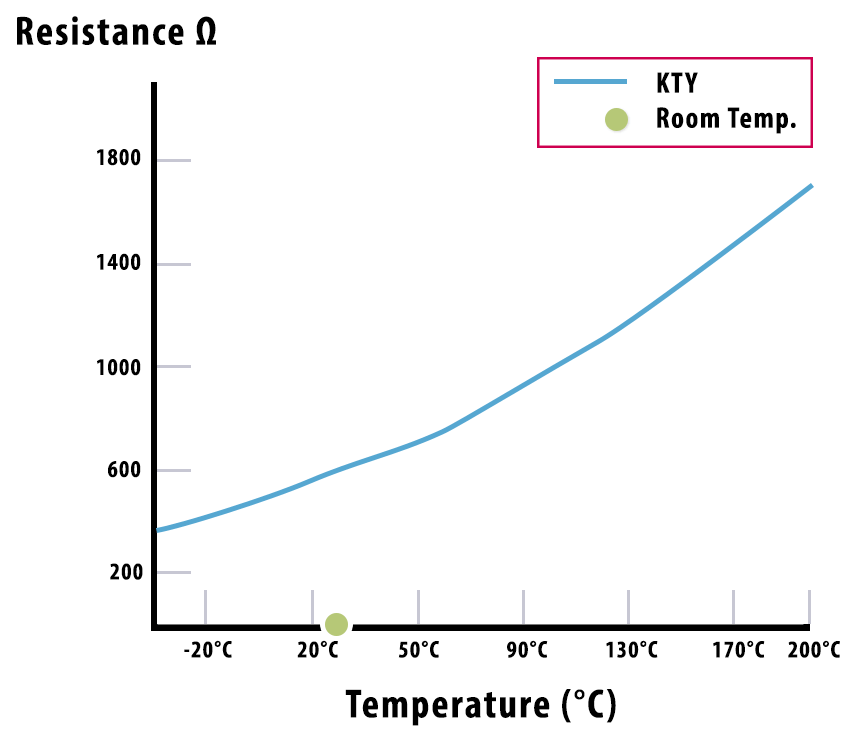
Image credit: KEB America
KTY sensors have a high degree of stability (low thermal drift) and nearly constant temperature coefficient, and are also typically lower cost than PTC thermistors. While both PTC thermistors and KTY sensors are commonly used for monitoring winding temperature in motors and gearmotors, KTY sensors are more prevalent in large or high-value motors, such as iron core linear motors, due to their high accuracy and linear behavior.
Feature image credit: Electro Technical Officer
Leave a Reply
You must be logged in to post a comment.