• Skip to primary navigation
  • Skip to main content
  • Skip to primary sidebar
  • Skip to footer
  • Advertise
  • Subscribe

Motion Control Tips

Automation • Motion Control • Power Transmission

  • News
    • Industry News
    • Editor Blogs
  • Controls
    • HMIs
    • PC-Based Controllers
    • PLCs + PACs
    • Stand-Alone Controllers
    • Software
  • Drives
    • Servo Drives
    • Stepper Drives
  • Encoders
    • Absolute Encoders
    • Incremental Encoders
    • Rotary Encoders
  • Mechanical
    • Bearings
    • Brakes + Clutches
    • Belt + chain
    • Couplings
    • Gears + Gearing
    • Lubrication
    • Shock + Vibration Mitigation
    • Springs + Rings + Seals
  • Linear
    • Actuators
    • Linear Motors
    • Linear Encoders
  • Motors
    • AC Motors
    • DC Motors
    • Brushless Motors
    • Gearmotors
    • Piezo Motors
    • Servo Motors
    • Stepper Motors
  • Systems
    • Conveyors + linear transport systems
    • Gantries + Stages
    • Rotary Tables
    • Grippers + End Effectors
    • Robotics
  • Networks
    • Connections + Sliprings
    • Fieldbuses
    • I/O
    • Sensors + Vision
  • Resources
    • FAQs
      • Motion Casebook
      • Motion Selection Guides
    • Suppliers
    • Video
You are here: Home / FAQs + basics / What is a gated index pulse for incremental encoders?

What is a gated index pulse for incremental encoders?

July 7, 2020 By Danielle Collins Leave a Comment

Incremental encoders typically use two square-wave signals in quadrature (out of phase by 90 degrees) to track position and direction of motion. But because they only track incremental position (not absolute position) they’re not able to determine the true position of the motor and connected equipment after a shut-down or power loss. So most incremental encoders also include a third signal — typically referred to as the index pulse — which helps determine the actual position of the motor during startup.

The two primary signals are produced on the A and B channels, and the index pulse is produced on a third channel, commonly referred to as the “Z” or “I” channel.


Unlike the primary signals, which produce continuous square waves, the index pulse is a single pulse produced once during each shaft rotation, indicating a fixed, discrete position in the mechanical rotation (or linear movement) of the encoder. Therefore, the index pulse can be used not only to determine the position of the motor during startup, it can also be used as a counter to track the number of shaft rotations, or to reset a position counter.

The index pulse is also referred to as a marker pulse, home, or zero reference.

The index pulse in an incremental encoder can be either gated or ungated. Gating refers to whether the pulse is referenced to, or aligned with, one or both of the primary channels — A and/or B. An ungated index pulse typically has a length of 360 electrical degrees or larger, and the edges of the pulse have no definite correlation to either the A or B channel. A gated index pulse is truncated to either 180 or 90 electrical degrees and provides a more accurate reference position.

gated index pulse
With quarter-cycle gating, the index pulse is gated to both the A and B channels, meaning it is high for the 90 degrees of the cycle in which both the A and B channels are high (or when both are low). With half-cycle gating, the index pulse is gated to either the A or B channel, when the channel is high or low. In this case, the index pulse width will be 180 electrical degrees.
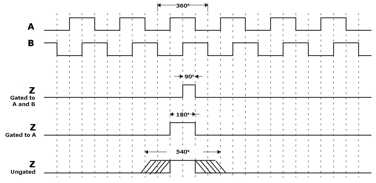
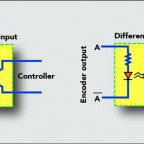
Image credit: Texas Instruments

Index pulses that are gated to either the A or B channel have a width of 180 electrical degrees. This is referred to as half-cycle gating (with a full cycle being 360 electrical degrees). While the index pulse can be gated to either the high or the low state of the A or B channel, it is most often gated to the high state (A high or B high).

Similarly, index pulses that are gated to both the A and B channels in their high state (or to both the A and B channels in their low state) have a length of 90 electrical degrees. This is referred to as quarter-cycle gating.

Whether an index pulse is ungated, half-cycle gated, or quarter-cycle gated depends on the encoder model. And while gating improves the accuracy of the index pulse — and in turn, the home or reference position — it requires that the servo drive or controller be able to read the Z channel at a rate fast enough to detect the pulse with every revolution of the encoder.

You Might Also Like

Filed Under: Encoders, FAQs + basics, Featured, Incremental Encoders, Rotary Encoders

Reader Interactions

Leave a Reply

You must be logged in to post a comment.

Primary Sidebar

LEARNING CENTER

Design World Learning Center

Motion Control Handbook

“mct
EXPAND YOUR KNOWLEDGE AND STAY CONNECTED
Get the latest info on technologies, tools and strategies for Design Engineering Professionals.

RSS Featured White Papers

  • Robotic Automation is Indispensable for the Logistics Industry’s Continued Growth and Success
  • Reliable Linear Motion For Packaging Machines
  • Polymers Outperform Metals In Precision Gearing

Footer

Motion Control Tips

DESIGN WORLD NETWORK

Design World Online
The Robot Report
Coupling Tips
Linear Motion Tips
Bearing Tips
Fastener Engineering.
Wire and Cable Tips

MOTION CONTROL TIPS

Subscribe to our newsletter
Advertise with us
Contact us
About us

Copyright © 2025 · WTWH Media LLC and its licensors. All rights reserved.
The material on this site may not be reproduced, distributed, transmitted, cached or otherwise used, except with the prior written permission of WTWH Media.

Privacy Policy | RSS