Updated February 2020 || The function of a gear is to mesh with other gears to transmit altered torque and rotation. In fact, gearing can change the speed, torque and direction of motion from a drive source.

Geometry
& general gear design
When two gears with an unequal number of teeth engage, the mechanical advantage makes their rotational speeds and torques different.
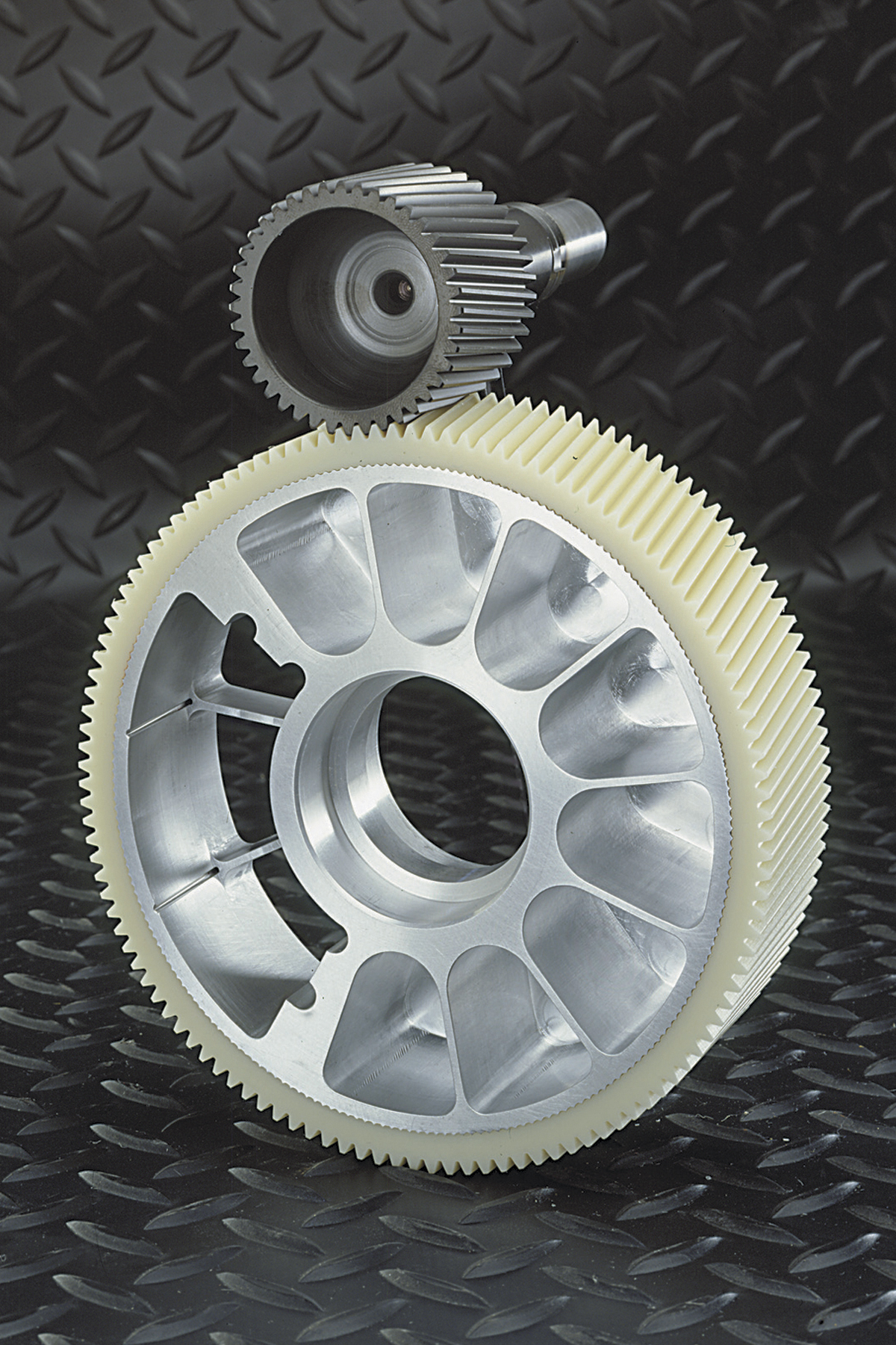
In the simplest setups, gears are flat with spur teeth (with edges parallel to the shaft) and the input gear’s shaft is parallel to that of the output. Spur gears mostly roll through meshing, so can be 98% or more efficient per reduction stage. However, there is some sliding between tooth surfaces, and initial tooth-to-tooth contact occurs along the whole tooth width at once, causing small shock loads that induce noise and wear. Sometimes lubrication helps mitigate these issues.
In slightly more complex setups, parallel-axis gearsets have helical gears that engage at an angle between 90° and 180° for more tooth contact and higher torque capacity. Helical reducers are suitable for higher-horsepower applications where long-term operational efficiency is more important than initial cost. Helical gear teeth engage gradually over the tooth faces for quieter and smoother operation than spur gearsets. They also tend to have higher load capacities.
One caveat: Angled tooth contact generates thrust that the machine frame must resolve.
No matter the subtype, most parallel-axis gearsets have gear teeth with tailored involute profiles—customized versions of the rolled trace off a circle with an imaginary string. Here, mating gears have tangent pitch circles for smooth rolling engagement that minimizes slipping. A related value, the pitch point, is where one gear initially contacts its mate’s pitch point.
Involute gearsets also have an action path that passes through the pitch point tangent to a base circle.
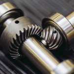
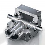
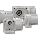
Besides parallel-axis gearsets, there are non-parallel and right-angle gearsets. These have input and output shafts that protrude in different directions to give engineers more mounting and design options. The gear teeth of such gearsets are either bevel (straight, spiral or zerol), worm, hypoid, skew or crossed-axis helical gears. The most common are bevel gearsets with teeth cut on an angular or conical shape.
Hypoid gears are much like spiral-bevel gearsets, but the input and output shaft axes don’t intersect, so it’s easier to integrate supports. In contrast, zerol gearsets have curved teeth that align with the shaft to minimize thrust loads.
General speed reducers, shaft-mount sets
& worm drives
Gear reducers, called speed reducers, are a component of many mechanical, electrical and hydraulic motors. Essentially, it is a gear or series of gears combined in such a manner as to alter the torque of a motor. Typically, the torque increases in direct proportion to the reduction of rotations per unit of time.
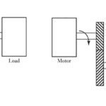
Speed reducers come in two varieties: base mounted and shaft mounted. Shaft-mounted types come in two versions. One is truly shaft mounted in that the input shaft of the drive motor supports it … with a special coupling to address torque reactions. The other mounts to the machine housing so the input shaft doesn’t support the reducer’s weight or address torque reactions.
By the American Gear Manufacturers Association (AGMA) definition, engineers apply the term “speed reducer” to units operating at pinion speeds below 3,600 rpm or pitch-line velocities below 5,000 fpm. (The AGMA is an international group of gear manufacturers, consultants, academics, users and suppliers.)
Reducers operating at speeds higher than these are called high-speed units. Manufacturers base catalog ratings and engineering specifications for speed reducers on these AGMA standards.
(More after the illustration.)
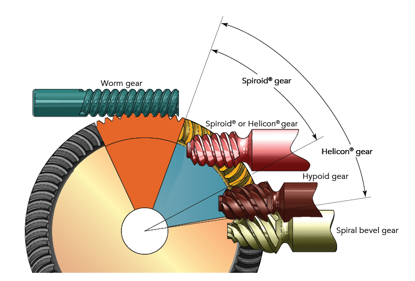
There are as many types of speed reducers as there are gear types. Consider reducers in which the input and output shafts are at different angles. The most common of these are worm-gear reducers.
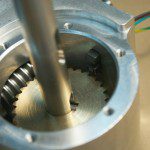
Worm-gear reducers are used in low- to moderate-horsepower applications. They offer low initial cost, high ratios and high output torque in a small package, along with a higher tolerance for shock loading than helical gear reducers. In a traditional setup, a cylindrical toothed worm engages a disk-shaped wheel gear with teeth on its circumference or face.
(More after the video.)
Most worm gears are cylindrical with teeth of consistent size. Some worm-gear reducers use a double-enveloping tooth geometry—with a pitch diameter that goes from deep into short and back to deep—so more teeth engage. No matter the version, most wheel gears in worm-based reducers sport cupped teeth edges that wrap around the worm shaft during engagement. In many cases, the sliding engagement lowers efficiency but extends life, as worm-gear mating holds a film of lubricant during operation. The ratio of a worm-gear is the number of wheel teeth to the number of threads (starts or leads) on the worm.
A few words on gearheads
A gearhead is similar to a gear reducer, but a gearhead doesn’t just reduce speed. Engineers use them wherever an application calls for high torque at low speed. It reduces a load’s reflected mass inertia, which makes accelerating heavy loads easier, enabling designs to run off smaller motors. Gearheads come in a variety of styles from basic spur gearheads to more complex planetary gearheads and harmonic type gearheads, each with their own characteristics and suitable applications. One caveat: In some applications, gearhead backlash is an issue. In this case, consider using a gearhead with low or zero backlash.
Gearboxes, specialty gearheads & servo gearsets … including planetary sets
Servo systems are precision-motion setups with feedback and (in most cases) fairly stringent accuracy demands. So for these designs, engineers should pick servogear reducers with good torsional stiffness, reliable output torque and minimal backlash. OEMs tasked with integrating servo systems should look for quiet reducers that easily mount to the motor and require little or (if possible) no maintenance.
In fact, a lot of advanced machinery integrates servogears into application-specific electromechanical arrangements, and several of these arrangements are common enough to have specific labels. Here is a look at some of the most widespread.
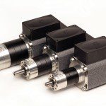
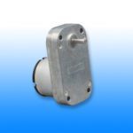
Gearmotor: This complete motion component is a gear reducer integrated with an ac or dc electric motor. Usually the motor includes the gears on its output (typically in the form of an assembled gearbox) to reduce speed and boost available output torque. Engineers use gearmotors in machines that must move heavy objects. Speed specifications for gearmotors are normal speed and stall-speed torque.
Gearbox: This is a contained gear train … a mechanical unit or component consisting of a series of integrated gears. Planetary gears are common in integrated gearboxes.
Planetary gears: Particularly common in servo systems, these gearsets consist of one or more outer planet gears that revolve about a central, or sun, gear. Typically, the planet gears mount on a movable arm or carrier that rotates relative to the sun gear. The sets often use an outer ring gear, or annulus, that meshes with the planet gears.
The gear ratio of a planetary set requires calculation, because there are several ways they can convert an input rotation to an output rotation. Typically, one of these three gear wheels stays stationary; another is an input that provides power to the system, and the last acts as an output that receives power from the driving motor. The ratio of input rotation to output rotation depends on the number of teeth in each gear and on which component is held stationary.
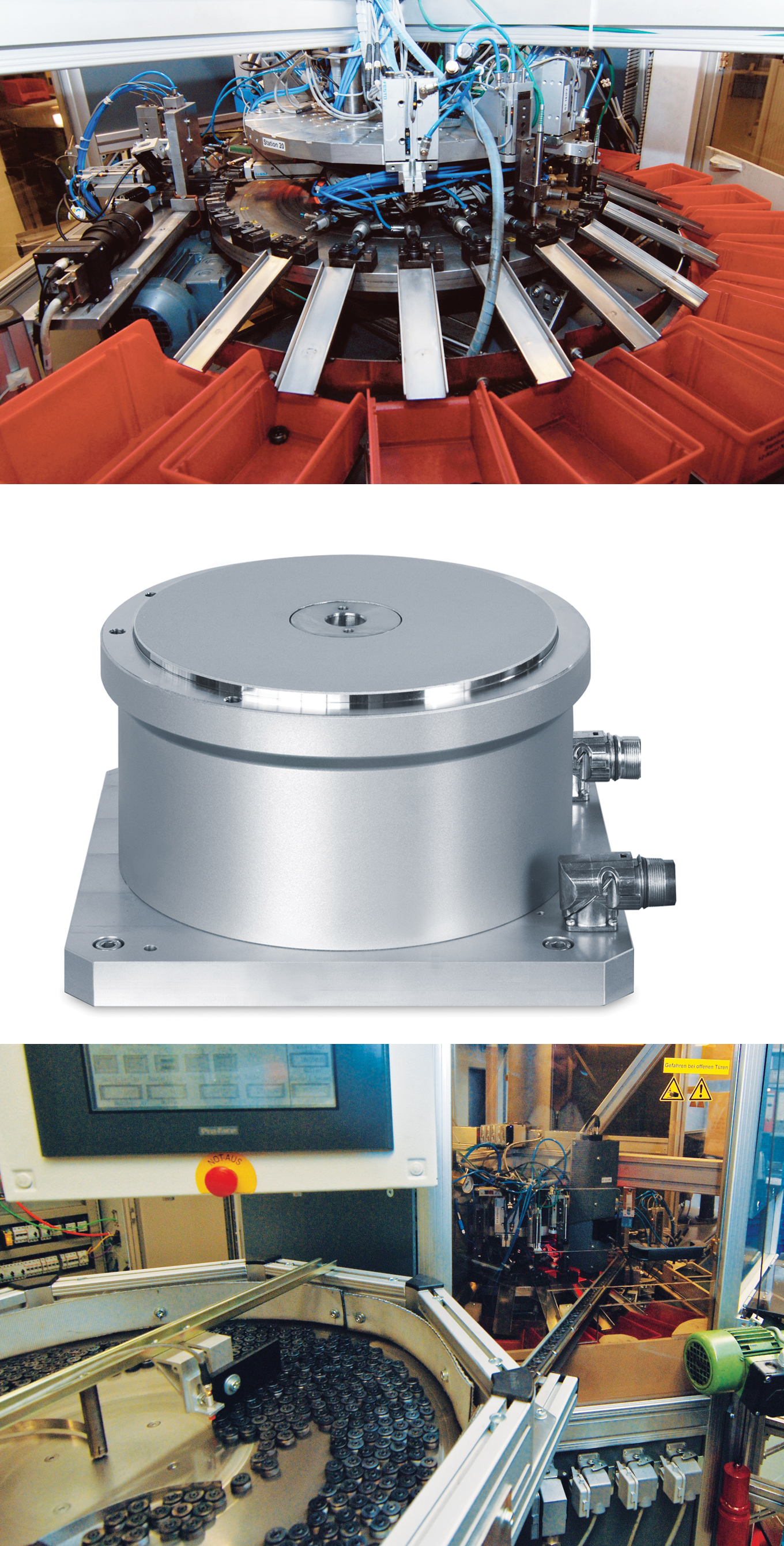
Planetary gearsets offer several advantages over other gearsets. These include high power density, the ability to get large reductions from a small volume, multiple kinematic combinations, pure torsional reactions and coaxial shafting. Another advantage to planetary gearbox arrangements is power-transmission efficiency. Losses are typically less than 3% per stage, so rather than waste energy on mechanical losses inside the gearbox, these gearboxes transmit a high proportion of the energy for productive motion output.
Planetary gearbox arrangements distribute load efficiently, too.
Multiple planets share transmitted load between them, which greatly increases torque density. The more planets in the system, the greater load ability and the higher the torque density. This arrangement is also very stable due to the even distribution of mass and increased rotational stiffness. Disadvantages include high bearing loads, inaccessibility and design complexity.
In servo systems, besides boosting output torque, gearboxes impart another benefit—reducing settling time. Settling time is a problem when motor inertia is low compared to load inertia … an issue that’s the source of constant debate (and regular improvement) in the industry. Gearboxes reduce the reflected inertia at the controls by a factor equal to the gear reduction squared.
Strain-wave gearing
Strain-wave gearing is a special gear design for speed reduction. It uses the metal elasticity (deflection) of a gear to reduce speed. (Strain-wave gearing sets are also known as Harmonic Drives, a registered trademark term of Harmonic Drive Systems Inc.) Benefits of using strain-wave gearing include zero backlash, high torque, compact size and positional accuracy.
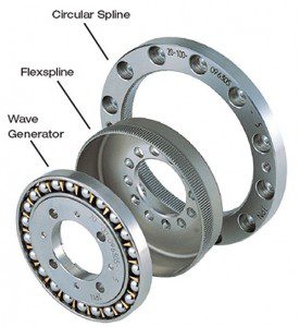
A strain-wave gearset consists of three components: wave generator, flexspline and circular spline.
The wave generator is an assembly of a bearing and a steel disk called a wave generator plug. The outer surface of the wave generator plug has an elliptical shape machined to a precise specification. A specially designed ball bearing is pressed around this bearing plug causing the bearing to conform to the same elliptical shape of the wave generator plug. Designers typically use the wave generator as the input member, usually attached to a servomotor.
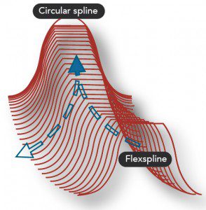
The flexspline is a thin-walled steel cup. Its geometry lets the walls of the cup be radially compliant but remain torsionally stiff (because the cup has a large diameter). Manufacturers machine the gear teeth into the outer surface near the open end of the cup (near the brim). The flexspline is usually the output member of the mechanism.
The cup has a rigid boss at one end to provide a rugged mounting surface. The wave generator is inserted inside the flexspline so the bearing is at the same axial location as the flexspline teeth. The flexspline wall near the brim of the cup conforms to the same elliptical shape of the bearing. This conforms the teeth on the outer surface of the flexspline to the elliptical shape. That way, the flexspline effectively has an elliptical gear-pitch diameter on its outer surface.
The circular spline is a rigid circular steel ring with teeth on the inside diameter. It is usually attached to the housing and does not rotate. Its teeth mesh with those of the flexspline. The tooth pattern of the flexspline engages the tooth profile of the circular spline along the major axis of the ellipse. This engagement is like an ellipse inscribed concentrically within a circle. Mathematically, an inscribed ellipse contacts a circle at two points. However, the gear teeth have a finite height. So there are actually two regions (instead of two points) of tooth engagement. Roughly 30% of the teeth are engaged at all times.
The elastic radial deformation acts like a very stiff spring to compensate for space between the teeth that would otherwise increase backlash.
The pressure angle of the gear teeth transforms the output torque’s tangential force into a radial force acting on the wave-generator bearing. The teeth of the flexspline and circular spline engage near the ellipse’s major axis and disengage at the ellipse’s minor axis. Note that the flexspline has two less teeth than the circular spline, so every time the wave generator rotates one revolution, the flexspline and circular spline shift by two teeth. The gear ratio is calculated:
number of flexspline teeth ÷ (number of flexspline teeth – number of circular spline teeth)
The tooth engagement motion (kinematics) of the strain wave gear is different than that of planetary or spur gearing. The teeth engage in a manner that lets up to 30% of the teeth (60 for a 100:1 gear ratio) engage at all times. This contrasts with maybe six teeth for a planetary gear, and one or two teeth for a spur gear.
In addition, the kinematics enable the gear teeth to engage on both sides of the tooth flank. Backlash is the difference between the tooth space and tooth width, and this difference is zero in strain-wave gearing.
(More after the gallery. Click on the photos for larger versions.)
As part of the design, the manufacturer preloads the gear teeth of the flexspline against those of the circular spline at the major axis of the ellipse.
The preload is such that the stresses are well below the material’s endurance limit. As the gear teeth wear, this elastic radial deformation acts like a stiff spring to compensate for space between the teeth that would otherwise cause an increase in backlash. This lets the performance remain constant over the life of the gear.
Strain-wave gearing offers high torque-to-weight and torque-to-volume ratios. The lightweight construction and single-stage gear ratios (of up to 160:1) let engineers use the gears in applications requiring minimum weight or volume. Small motors can exploit the large mechanical advantage of a 160:1 gear ratio to create a compact, lightweight and low-cost package.
Another tooth profile for strain-wave gearing is the S tooth design. This design lets more gear teeth engage. The effect is to double torsional stiffness, double peak torque ratings and lengthen operational life. The S tooth form doesn’t use the involute curve of a tooth. Instead, it uses a series of pure convex and concave circular arcs that match the loci of engagement points dictated by theoretical and CAD analysis.
The increased root filet radius makes the S tooth much stronger than an involute curve gear tooth. It resists higher bending (tension) loads while maintaining a safe stress margin.
Read the related article: How to Select a Gearmotor in Four Simple Steps






Leave a Reply
You must be logged in to post a comment.