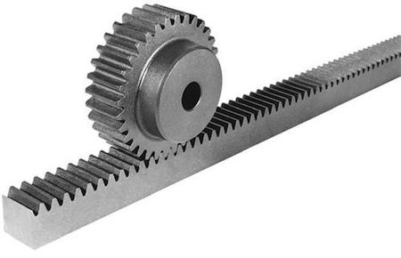
A rack and pinion drive system consists of a rack (or a “linear gear”) and a pinion (or “circular gear”). The teeth of a rack and pinion drive can be straight or helical, although helical teeth are often used due to their higher load capacity and quieter operation. For a rack and pinion drive system, the maximum force that can be transmitted is largely determined by the tooth pitch and the size of the pinion.
These systems are well-established linear drive mechanisms, providing high-speed travel over extremely long lengths. They are frequently used in large gantry systems for material handling, machining, welding and assembly, especially in the automotive, machine tool, and packaging industries.

Rack and pinions can be constructed in nearly unlimited lengths. Rack sections can be joined endlessly, although the guide mechanism (a profiled rail or cam roller, for example) can be the limiting factor in maximum stroke length. Rack and pinion systems can operate in one of two ways: with the pinion (including gearbox and motor) moving and the rack stationary, or with the pinion assembly stationary and the rack moving.
Rack and pinion drive systems do have backlash, due to the meshing of gear teeth. But high precision helical rack and pinion systems have tooth pitch errors in the single-micron range. It’s also possible to preload a rack and pinion system to prevent backlash.
Lubrication is critical for rack-and-pinion systems due to the metal-on-metal contact combined with the tight clearances between gear teeth. Automatic lubrication systems are recommended for use with rack and pinions to ensure proper lubrication and avoid reduced performance or even failure.


Leave a Reply
You must be logged in to post a comment.