
The basic operation of an electric motor relies on the interaction between the rotor’s permanent magnets and the stator’s energized windings. But even when the motor is not powered and no current is flowing though the windings, there is a magnetic attraction between the permanent magnets of the rotor and the ferromagnetic teeth of the stator. The magnetic attraction varies depending on the flux density, or strength, of the magnetic fields, and this variation causes uneven torque production, which is referred to as “cogging torque” or “torque ripple.”
While these two terms are sometimes used interchangeably, cogging torque generally refers to the phenomenon that causes torque variations, and torque ripple is the effect these variations have on motor performance.
Cogging torque
Cogging torque is a product of the magnetic interaction between the poles of the rotor’s permanent magnets and the steel laminations of the stator’s teeth. In other words, when the poles of the rotor line up with the teeth of the stator, a force is required to break the attraction, and this force is referred to as cogging torque. Cogging torque is position-dependent, according to the location of the stator teeth relative to the permanent magnets, as the magnets constantly search for a position of minimum reluctance.
A motor’s cogging torque profile depends on the number of permanent magnets in the rotor and the number of teeth in the stator and can be minimized through mechanical means by optimizing the number of magnetic poles and teeth, or by skewing or shaping the permanent magnets to make their transition between stator teeth more gradual.
Cogging torque occurs in permanent magnet motors, including brushed and brushless DC motors and synchronous AC motors. Because it occurs in an un-energized motor, it is sometimes referred to as “open-circuit torque.”
Torque ripple
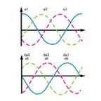
The result of cogging torque is a variation in torque production — referred to as torque ripple — that occurs when the motor is energized with constant current. Due to the nature of the interaction between the magnetic fields of the rotor and the stator (described above), torque ripple varies sinusoidally. At high speeds, it is often filtered out by the inertia of the system, but at lower speeds, torque ripple can cause unwanted speed fluctuations, vibrations, and audible noise.
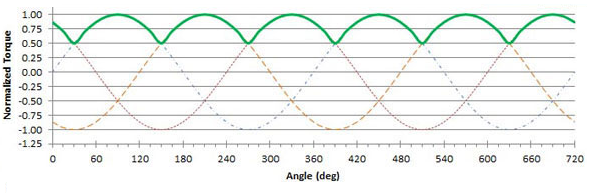
Image credit: Precision Microdrives Limited
Cogging in stepper motors
Stepper motors also exhibit cogging torque, but in stepper motor discussions, it is often referred to as “detent torque.” Like cogging torque, detent torque is a result of magnetic equilibrium in a non-energized motor. This magnetic equilibrium must be overcome before the motor will rotate, which means that the detent torque reduces the amount of running torque the motor can produce. The amount of detent torque a stepper motor experiences is proportional to the motor’s speed, so the effect of detent torque on running torque is more substantial at higher motor speeds.
Permanent magnet and hybrid stepper motors, which use a permanent magnet rotor, exhibit detent torque; but variable reluctance steppers, which use a non-magnetized, soft iron rotor, do not. Of permanent magnet and hybrid types, hybrid steppers have higher detent torque due to their toothed rotors, which allows them to better manage the magnetic flux between the stator and the rotor.
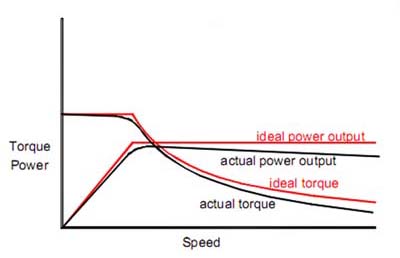
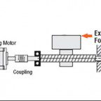
Image credit: Geckodrive Motor Controls
Detent torque is typically 5 to 20 percent of the motor’s holding torque, which is the amount of torque the motor can produce when the windings are energized but the rotor is stationary. But detent torque is not always a liability: When the motor is decelerating, it counters the motor’s momentum and helps it to stop more quickly.

Leave a Reply
You must be logged in to post a comment.