
Absolute encoders can communicate with controllers through parallel or serial wiring, over a fieldbus, or via an Ethernet-based protocol such as EtherCAT. Of these options, serial communication is a simpler solution than parallel wiring (which requires a twisted pair of wires for each bit of output) and is well-suited for applications that aren’t complex enough to justify a fieldbus or Ethernet-based protocol. Here, we’ll look at the differences between four of the most common absolute encoder serial interfaces available today: SSI, BiSS, Hiperface DSL, and EnDat 2.2.
SSI: Synchronous Serial Interface
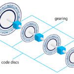
As its name suggests, SSI is a synchronous protocol, meaning that data is transferred from the encoder to the controller synchronously via a clock signal, or pulse, provided by the controller. The encoder output can be in binary or gray code, and one bit is transmitted per clock pulse, with standard word lengths of 13 bits for single-turn encoders and 25 bits for multi-turn encoders.
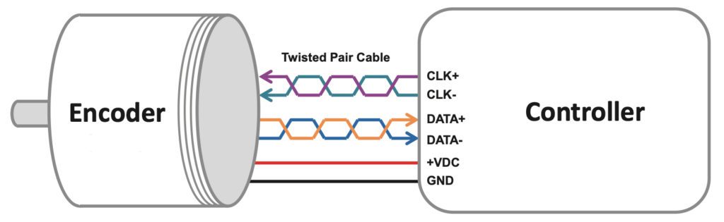
Image credit: AccuCoder
Synchronous Serial Interface uses two pairs of twisted wires for communication, per the RS-422 standard — one pair for differential data signals and one pair for differential clock signals. There are also two wires for power to the encoder. The clock frequency, or rate of data transmission, can be up to 1.5 MHz, depending on the length of the cable. To ensure data integrity, some SSI encoders support multiple transmission (also known as “multi-path” or “ringshift” transmission), in which the same data is sent multiple times and the controller compares the transmissions to ensure they match.
BiSS: Bidirectional Synchronous Serial Interface
The Bidirectional Synchronous Serial Interface is an open protocol and is similar to SSI in that data transmission is synchronized by clock signals from the controller, but with BiSS, clock speeds up to 10 MHz are possible. BiSS also uses two twisted pairs of wires — one pair for data signals and one pair for clock signals — plus two wires for power.
Unlike SSI, which only supports unidirectional communication, BiSS supports bidirectional communication, meaning the controller can read from and write to non-volatile memory in the encoder, where registers contain encoder identification information. BiSS encoders can also send data, such as temperature, to the controller on demand. Another unique feature of BiSS versus SSI is that within each data cycle, the master determines and compensates for any transmission delay, allowing data transmission rates up to 10 Mbps.
The most current version of BiSS is BiSS-C (C = Continuously), although the interface is typically referred to as simply “BiSS.”
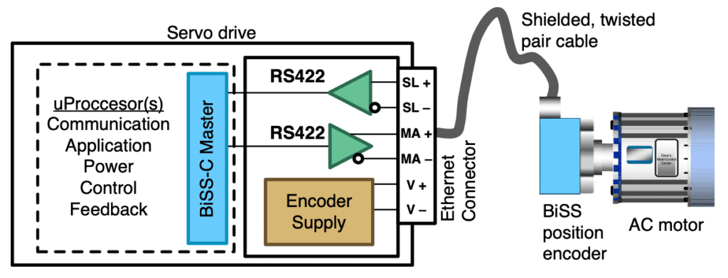
Image credit: Texas Instruments
Unlike SSI encoders, BiSS encoders can be connected point-to-point or via bus. When connected via bus, the data from all the encoders is clocked (synchronized) to the master in one continuous frame rather than individually. BiSS also implements a cyclic redundancy check (CRC) for error checking — a more reliable method than multiple transmission. There also exists a BiSS Safety interface, for safety applications up to SIL3 per IEC 61508.
Hiperface DSL
Hiperface DSL, the HIgh PERformance InterFACE Digital Servo Link, was originally a proprietary interface developed by SICK. However, in 2016, SICK “opened up” the interface with a licensing model that allows other manufacturers to integrate the technology into their product offering.
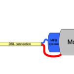
Unlike its predecessor, Hiperface, Hiperface DSL is an all-digital protocol that uses just two wires for bi-directional communication and encoder power, bundled with the motor power cable (although a transformer is required to improve the common mode noise rejection). This gives the advantage of eliminating the need for separate encoder connections on the motor and the controller. Hiperface DSL complies with the RS-485 standard and and has a data transmission rate of 9.375 Mbaud. Data can be transmitted cyclically (as fast as possible) or synchronously with the controller clock.
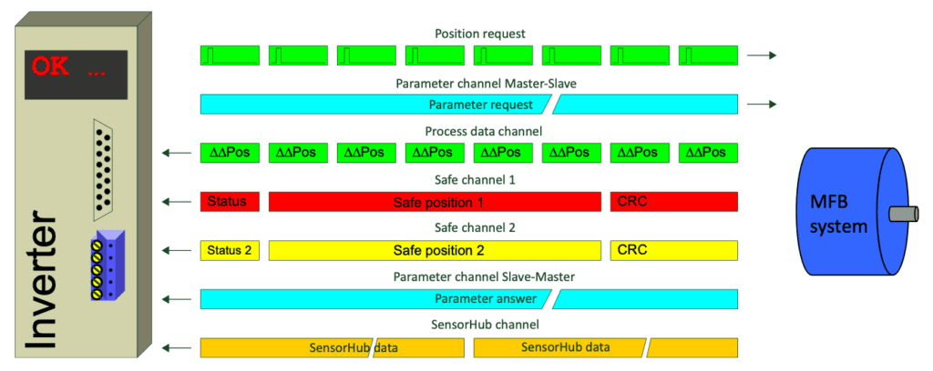
Image credit: Sick
The Hiperface DSL architecture also includes channels for the transfer of motor parameter data, condition monitoring data, and integrated safe motion, with data being transmitted over two digital communication wires. This redundancy and error-checking make the Hiperface DSL interface compliant with SIL3 safety standards.
EnDat 2.2
The Encoder Data, or EnDat 2.2, interface from Heidenhain is a synchronous, bidirectional standard that uses four wires for communication — two wires each for differential data and differential clock signals — plus two wires for power and two for either battery buffering or parallel power supply. EnDat 2.2 can provide clock frequencies of up to 2 MHz, and on some models, additional compensation for propagation delay makes frequencies up to 16 MHz possible.
Since Hiperface DSL has become an “open” interface, EnDat is now the only serial interface for absolute encoders that remains proprietary (although it should be noted that the original Hiperface protocol also remains proprietary).
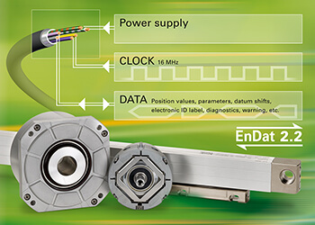
Image credit: Heidenhain
EnDat 2.2. can also read, write, or update information stored in the encoder and can transfer data such as sensor information or diagnostic information from the encoder to the controller. The type of data transmitted — for example, absolute position, diagnostics, or parameter information — is sent via mode commands from the controller to the encoder. Like BiSS and Hiperface DSL, EnDat 2.2. is also compliant with SIL3 safety standards.


Leave a Reply
You must be logged in to post a comment.