
Servo tuning can be accomplished by several methods, but the most common way is to use a PID algorithm. The PID algorithm uses three feedback gains—proportional gain, integral gain, and derivative gain—to compare the commanded position (or velocity) with the actual value and issue commands to correct errors between the two.
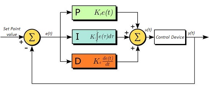
Feedback gains determine how hard the servo tries to correct or reduce the error between the commanded position and the actual position. Proportional gain is dependent on present error, integral gain is dependent on past error, and derivative gain is dependent on predicted future error.
Feedback gains
Proportional gain (Kp) determines the amount of restoring force (generated by the command voltage) that is applied to overcome the position error. The term “proportional gain” is used because its value is directly proportional to the positioning error. For example, if the proportional gain is 1.2 volts per encoder count, and the motor is 10 encoder counts from the commanded position, the command voltage will be 12.0 volts.
Proportional gain is the most important component of the PID algorithm, but a Kp value that is too high can cause the system to oscillate, to become under-damped, or to become unstable.
Often, as the servo controller works to decelerate the motor by reducing the command output, system friction overcomes the command voltage and causes the motor to fall short of the target.
Integral gain (Ki) overcomes this by producing a command that “pushes” the system to zero positioning error at the end of the move. The term “integral gain” is used because its command increases over time at the end of the move.
If sufficient positioning accuracy is achieved with the proportional gain, then integral gain may not be necessary. However, it is useful when steady-state (static) positioning is difficult to hold due to system disturbances, or when constant velocity motion is required.
Derivative gain (Kd) determines the restoring force that is proportional to the rate of change (derivative) of the positioning error. It works in conjunction with proportional gain to dampen the system response and reduce overshoot and oscillations.
Servo instability can occur if the derivative gain value is calculated too frequently, as it will begin to work against, rather than with, the proportional gain. To avoid this, the derivative sampling period can be increased.
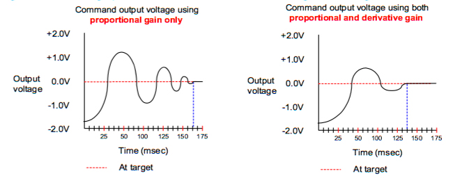
Image credit: PMC Corporation
Overshoot limits
Derivative gain is used to set the overshoot limit, or the acceptable amount by which the servo can exceed the target position. While perfectly accurate positioning is desirable in theory, in real world applications, an overshoot limit that is too small will likely cause the system to be over-damped. Conversely, a very high overshoot limit gives good system response, but can lead to oscillations.
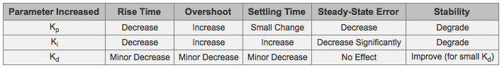
Image credit: Thorlabs, Inc.
Position error limits
The principle behind servo control is the comparison of the system’s actual value versus the commanded value, and the difference between the commanded and actual position is the position error (also referred to as the “following error). As seen above, the purpose of feedback gains is to reduce the position error. The position error limit, however, is used to indicate a problem with the servo or with the tuning algorithm. The position error limit should be set to a value that would not be seen during normal operation, and the controller response should be programmed to stop the axis when this limit is reached or exceeded.
Leave a Reply
You must be logged in to post a comment.