
Reflected waves, also known as transmission line effects or standing waves, are over-voltages that can damage the motor and cable. The use of IGBTs (insulated gate bipolar transistors) in variable frequency drives has helped to improve VFD performance in several ways. First, their quick switching time (also referred to as rise time, or dV/dt) means lower energy losses, which allows for less cooling and smaller designs. IGBTs also permit the VFD to use a higher carrier frequency for sending output voltage pulses to the motor, which reduces audible motor noise and provides the motor with reduced harmonics and lower peak current. Lower peak current enables the motor to run cooler and develop more torque-producing current throughout the speed range.
On the flip side, IGBTs have brought to light the phenomenon of reflected waves. Also known as transmission line effects or standing waves, reflected waves are over-voltages that can damage motor insulation and cables.
Causes of reflected waves
Most VFDs today operate via pulse width modulation (PWM), with the inverter producing a continuous train of pulses rather than sinusoidal wave forms. These voltage pulses are transmitted to the motor terminals through the motor cable. The cable’s inductance (a factor of impedance) is proportional to the length of the cable. High inductance, due to long cable lengths, increases the amount of time it takes to charge the capacitance of the motor, which increases the amount of energy in the cables.
Inductance is a conductor’s resistance to change in electric current, and capacitance is the ability to store an electrical charge. Both are impeding mechanisms and present an opposition to current when voltage is applied. The collective impedance caused by inductance and capacitance is known as reactance.
Additionally, when the voltage pulses reach the motor, they encounter a different (higher) impedance than in the cable, causing the pulses to be reflected back to the drive. Under certain conditions, a pulse from the VFD can add to a pulse reflected back from the motor, resulting in a doubling of the voltage level. The greater the length of the cable (i.e. the distance between the motor and the VFD), the greater the over-voltage, or reflected wave.
Together with cable length, the rise time of the switching device also has an effect on reflected waves and the amount of voltage overshoot. If the turn-on time of the switching device is slow, the capacitance of the motor has time to charge and discharge in step with the switching device. But if the switching device’s turn-on time is very fast, the voltage applied across the cable increases, and more energy is stored, resulting in a higher over-voltage.
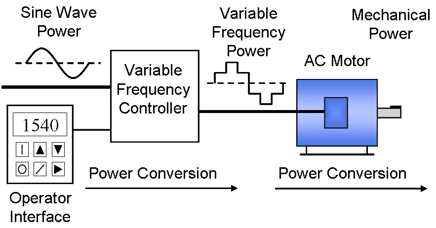
Image credit: C. J. Cowie, Wikipedia.org
Effects of reflected waves
The problem with reflected waves is that the voltage spikes can ionize the air in the air gap between motor windings, as well as the air between the cable insulation and cable jacket, causing partial discharge, or corona. The point at which this ionization causes arcing across the motor windings (or across the conductors in the cable) is known as the corona inception voltage (CIV). When the motor CIV is reached, the insulation in the motor windings can be damaged or even fail. When the cable CIV is reached, a short-circuit can occur and the cable can be permanently damaged.
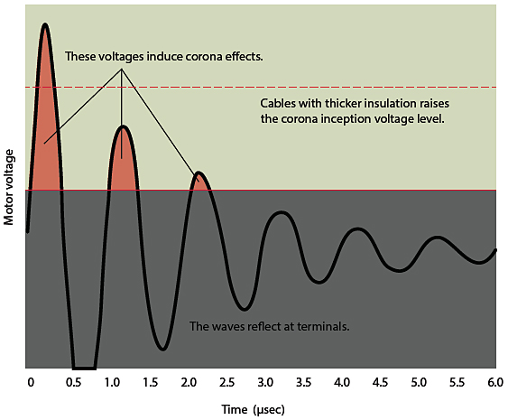
Image credit: SAB North America
Although reflected waves can occur regardless of the type of switching device—IGBT, GTO (gate turn off), or BJT (bipolar junction transistor)—the fast switching capability (rise time) of IGBTs makes this phenomenon more prevalent. Case in point: current IGBTs have turn-on times as fast as 0.1 ms, where BJTs switch at 0.5 to 1.0 ms, and GTOs switch at 15.0 to 20.0 ms.
Damage due to reflected waves is more prevalent with 460 volt and 575 volt IGBT-based drives. Drives that operate on 230 volts are rarely damaged due to voltage overshoot because the reflected waves have amplitudes that are lower than the motor CIV.
The most effective way to prevent the occurrence of reflected waves and over-voltage is to keep the cable length shorter than manufacturer’s recommended maximum. In cases where reducing the cable length isn’t feasible, there are hardware solutions, such as output reactors, filters, and terminator devices, that can reduce or eliminate reflected waves, protecting the motor and cable from damage.
Leave a Reply
You must be logged in to post a comment.