Addressing issues related to commutation alignment between AC PM servo motors and servo drive amplifiers — especially when motor and drive are from different manufacturers — can be quite challenging. Here we outline how to make that easier.
 By Hurley Gill • Senior applications and systems engineer | Kollmorgen
In this article, we’ll start by confirming the identification of a servo motor’s leads. Then we’ll move to confirming the identity of specific leads for a new drive’s phases — one for which firmware function labels have not yet been verified at the drive’s outputs. This will illustrate the basic issues of and solutions for ensuring commutation alignment.
The first question is motor related.
How can we confirm a manufacturer’s phase identification for a given permanent magnet (PM) AC servo motor?
The best way to confirm a motor’s phase identification is with an oscilloscope (OSC). But first let’s set four ground rules:
Motor rule one: We’ll identify the motor-phase nodes as A, B, and C (A, B, C) and assume the back or counter-electromotive force (Bemf) voltage at phase A leads that of phase B by 120° … and Bemf voltage at phase B leads that of phase C by 120° … and phase C Bemf voltage leads phase-A Bemf voltage by 120° relative to a defined direction of rotation of the motor’s rotor. Of course, these phases (nodes) could just as easily be identified as R, S, T or U, V, W.
Motor rule two: We will also identify phase A as the motor phase in which the feedback alignment is referenced — making it the motor’s anchor phase.
Motor rule three: Because the phases A, B, and C identify physical leads (nodes) of the motor’s Bemf or power source, we will identify the first positive or positive-going nodal voltage as phase A relative to the other node voltages. This will set a fixed starting point of the anchor phase — so we can approach analysis as if power was just applied and always started with phase A relative to the other phases.
Motor rule four: Phase-A voltage will be the positive leading voltage on every initial sequence under consideration — whether we are investigating the Bemf of a motor or the power source to a motor.
Phase A, B, C, clockwise (CW) rotation relative to a given direction of motor-rotor rotation — whether the reference is established by looking into the lead exit end of the motor or by its typical opposite end (the torque endbell) — does not matter as long as we are consistent. For the purposes of this article, we use phases A, B, and C for a clockwise (CW) rotation of the motor’s rotor as when viewed from the motor’s lead-exit end.
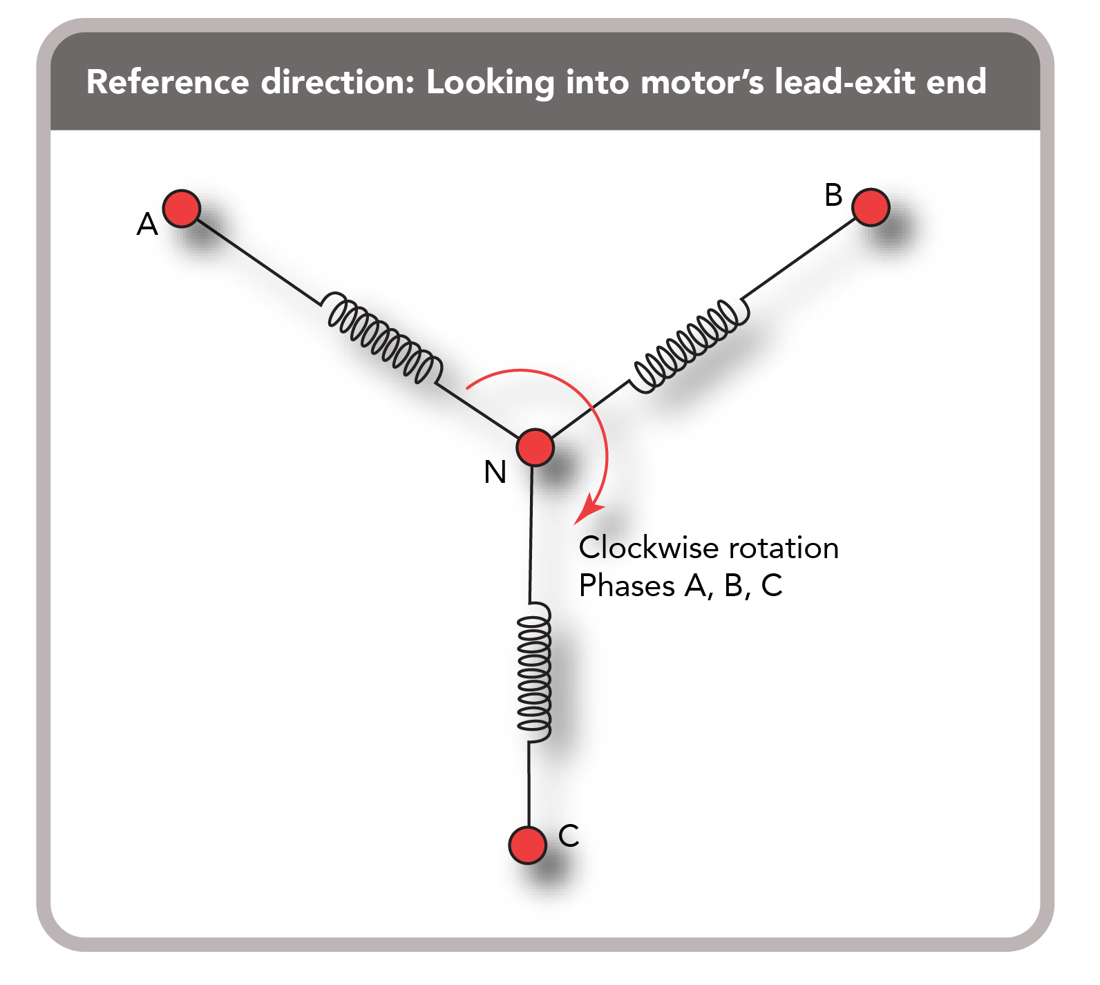
Identifying a servo motor’s phases is straightforward with a dual-channel oscilloscope. The latter allows engineers to check the relative relationship of a motor’s phases (Bemf waveforms) with the defined rotor rotation. For complete instructions of how this can be accomplished, refer to this article’s section titled, Deep dive on using an oscilloscope to observe motor waveforms.
Then by investigating how the Bemf node voltages relate to each other (VAB, VBC, VCA, VAB, VBC, and so on) your motor’s phases will successfully identified and labeled A, B, C as the servo motor’s rotor is rotated in its manufacturer’s defined direction. For our example in this article, we assume this direction is CW when looking into the lead exit end or typical rear endbell of our housed servomotor.
On a related note, the node VAB or VAB should be read as the voltage at node A with respect to node B. Each node is labeled for future reference this way — with only one specifically identified letter. There is good reason for this.
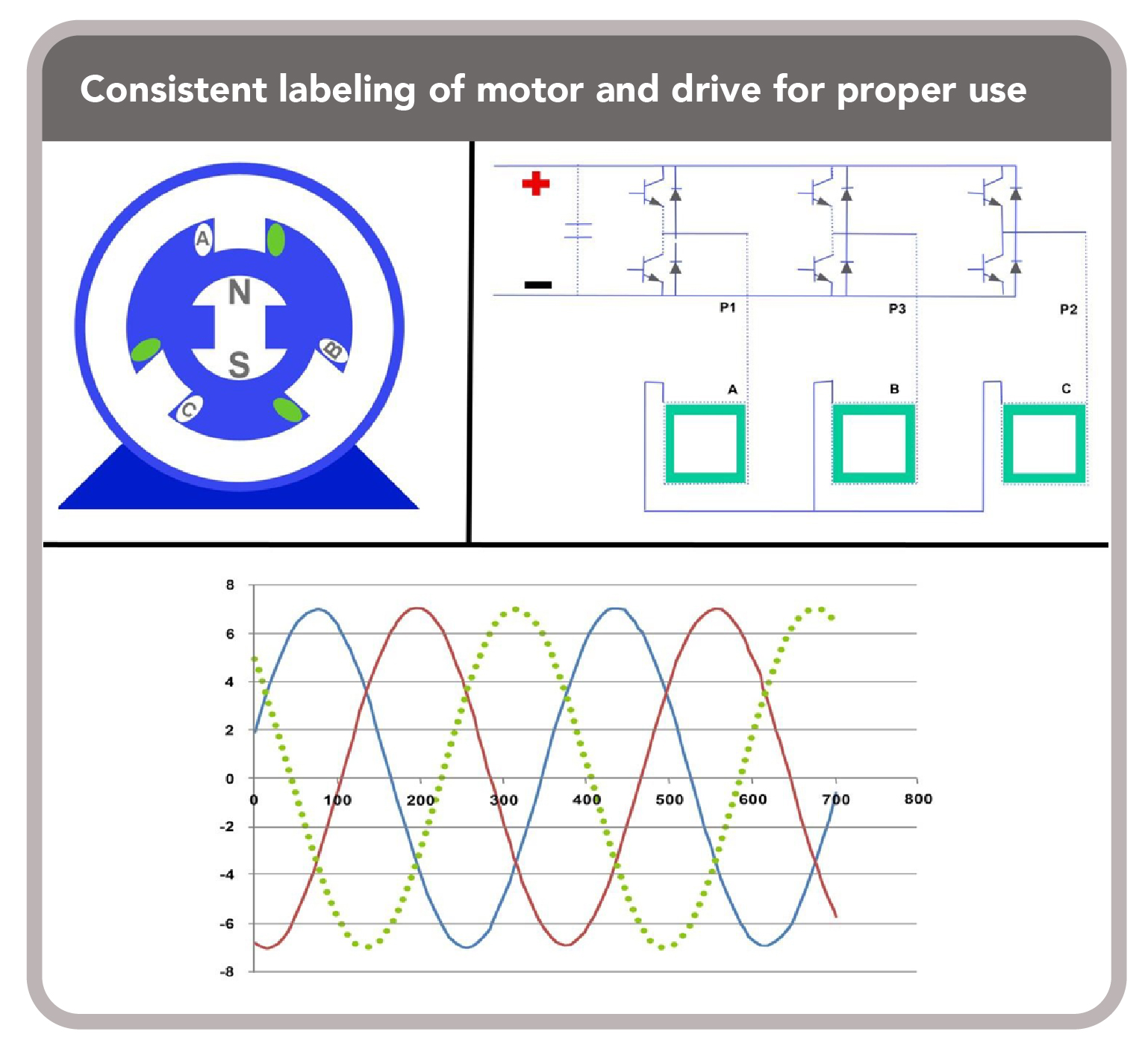
Our second question is drive related. Assume we have just designed a new servo drive and wish to maintain feedback commutation offsets and alignments so that harmony between products (including feedback commutation angles and so forth) is consistent.
What is the best procedure for maintaining such harmony between products?
This is a really good question — and for this example case, it’s clear we first had a permanent magnet (PM) AC synchronous motor that we want to drive as a servomotor — before having the drive amplifier to do so.
As with our motor investigation, let’s answer our drive-related question by first establishing some ground rules.
Drive rule one: Ensure that your past products’ motors and drives adhere to the identification methods of the motor phases you establish. These are a function of the motor’s Bemf generated when rotated in a defined direction.
Drive rule two: We must identify a specifically identified phase as an anchor we set as P1 (for the purposes of this article) with a feedback device. This anchor supply phase has a positive leading voltage on every initial sequence under consideration … as if power was just applied and always started with said anchor phase relative to all other phases. Again, this is something we assume for the purposes of this article. In actual operation the identified three phases are circling; defining one phase as an anchor sets a reference from which the hardware, software, and firmware are designed or can be designed (as for this example).
Drive rule three: For the purposes of this article, we define our drive phases as P1, P2, and P3 for a positive direction of rotation. That means the power supply for said positive direction of rotation includes output phase P1 leading P2 by 120° … and phase P2 leading P3 by 120° … and P3 leading P1 by 120°. Of course, we want the servo drive phases labeled A, B, and C on the released product — for labels consistent with the motor with which it integrates. However, until our programing within the drive has been confirmed, we are assigning the drive’s output phases as P1, P2, and P3 — where P1 is the drive’s anchor phase from which all hardware, software, firmware is designed and referenced with the expected feedback signal internal to the drive.
Drive rule four: We assume the drive will see a feedback signal counting up (positive) for the defined positive direction rotation (as set in drive rule three above) of the supplied phases. We also assume this positive commutation direction is the same as the motor’s defined commutation (CW) direction. We also assume all feedback connections are functionally the same as previous drives and motors. (They should be.)
Note: The commutation-angle setting on the drive depends on the alignment between the motor’s phases and feedback hardware. However, this setting is also a function of how the firmware and software within the drive is written; the number of motor pole pairs (electrical cycles) in one 360° motor-rotor rotation; and its original feedback alignment relative to motor phases.
One common mistake is to assign the drive phases A, B, and C with no intermediary step (of labeling them P1, P2, and P3) to confirm correct labeling and function. Another common mistake is to assign the drive phases A, B, and C with no upfront determination of how the motor needs to be supplied power for it to rotate in its defined direction.
At this stage it would be common and conceivably logical for the drive designer to establish the drive’s software, firmware, and physical circuitry so that positive electrical rotation output effectively places a positive voltage at the proposed motor’s anchor phase A (our P1) relative to phase B (our P2) … and then at phase B (P2) relative to phase C (our P3) …and finally, at phase C (P3) relative to phase A (P1). Expected feedback for the positive electrical-source rotation would count up and commutation phasing would be set with phase P1 as the drive’s anchor.
However, when drive phases are assigned upfront in this way, the prima facie (first impression) drive-to-motor connections are A to A, B to B, and C to C. This will quickly expose the connection fallacy — because the system won’t work. Why?
Such an assignment won’t work because supply voltages must be presented to each motor phase opposite the motor’s generated Bemf (for that same defined direction of rotation) as used to determine the individual motor phase (single letter) identification. We found motor phases A, B, C by the motor’s Bemf VAB, VBC, VCA, VAB, VBC, etc. specifically using a defined direction of rotation — a method utilized throughout the servomotor industry.
However, for the supply power to counter or appear, in opposition to the motor’s emf (Bemf for the defined direction of rotation) the drive’s output phase voltages must be presented to the motor as VAC, VBA, VCB, VAC, VBA, and so on against the Bemf of the motor. So, from the standpoint of our defined anchor phase, we must switch its reference — and not the anchor phase.
Note that the node VAC or VAC is read as the voltage at node A with respect to node C. This also demonstrates why only a single letter is used to define a specific motor and drive phase once appropriately defined.
The other item that is absolutely critical to maintaining commutation harmony between products is the identified drive phase anchor (herein P1) for matching up with the motor’s phase anchor (phase A). Note that the drive phase P1 does not have to be the anchor. In reality, one would want to assign the drive’s anchor phase in harmony with the anchor phase of the motor for which commutation alignment is to be maintained.
One might assume we can correct the problem by switching motor phase connections A and B at the drive. However, this will mismatch the motor’s anchor phase A against the drive’s anchor phase P1 and produce a commutation phase angle offset of ±120° against all previously manufactured motor-drive product line combinations … which also means it doesn’t meet our original requirements.
Of course, switching motor phases A and B is a common practice in the electrical industry for changing direction of rotation of an AC induction motor. But this solution is undesirable because our goal is to have consistent and sequential drive connection labels A, B, and C … and not B, A, and C as they appear on the drive. Just relabeling connections B, A, and C to A, B, and C (or C, B, and A) maintains an undesirable commutation-phase-angle offset against all previously manufactured motor-drive product line combinations (unless corrected within the drive’s software and firmware or by the circuit layout).
So, what would be the best way to avoid or correct this initial fallacy?
First, let’s return to the common and conceivably logical case of the drive designer establishing the drive’s software, firmware, and physical circuitry such that a positive electrical rotation would present an output effectively placing a positive voltage at the drive’s initially labeled output phase P1 relative to P2 … then phase P2 relative to phase P3 … and then phase P3 relative to phase P1. Expected feedback for the positive electrical-source rotation would count up with anchor phase established as P1.
Assuming drive-to-motor connections are P1 to motor phase A, P2 to B, and P3 to C,will yield a similar fallacy by suppling phase voltages with the Bemf relative to the desired defined direction rather that against the motor’s Bemf. So, what is the best way to correct and maintain the anchor phase of the drive P1 and the established motor anchor phase A?
The answer is that we flip the drive’s reference phase (so P2 connects to motor phase C) such that the drive’s supplied voltage is presented against the motor’s Bemf … and allowing the first phase (anchor P1) to be maintained per drives rule two listed above. This means drive phase P3 connects to motor phase B … and P1 to motor phase A is maintained.
Our progression for a final topology would be something like that seen in the figure, Progression for a final topology.
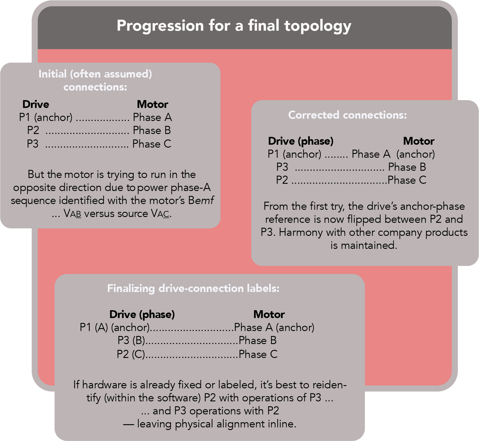
There are multiple connection scenarios that will produce a lack of desired operation during the design of a new drive. These different scenarios end up being of one variation or another of the one presented above. Usually the most important factor to respect during relabeling is the alignment of the drive’s anchor phase with the motor’s anchor phase. Otherwise, there is a ±120° offset and no possibility of product harmony with older and possibility present product lines.
Additional note: Whether or not the third labeling shown in the figure titled, Progression for a final topology requires some software and firmware changes will depend on the specifics of how the software and firmware was originally written or intended to work.
Also note that if Hall-effect devices (Halls) are being used, their drive association with their specific motor phase will also need to change depending on how the original firmware was written. If only the source reference for the anchor phase A is an issue, then redefining Hb (Hall-b) to be H_P3 and Hc to be H_P2 may complete the fix relative to drive P2 and P3. Review the Kollmorgen white paper titled, Servo Motor Phasing with Hall Commutation (pages T20-T22) at kollmorgen.com for more on this.
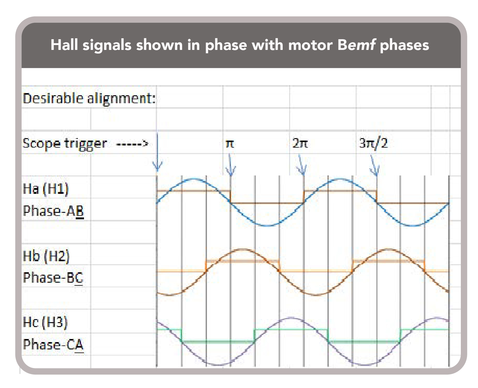
Observations: Product harmony between products should help sustain and improve product quality and safety — and ensure technology compliance between customers and suppliers for sustainable design and manufacturing practices. To use a metaphor, the identified anchor phase during design should be as fixed as the Sword of the Stone — impossible for a non-rightful claimant to take. “If the sword is moved, it moves with the stone, it being fixed within.”
Of course, there are many ways to mix and match motor phases, Hall signals, resolver signals, and other feedback devices to get a working system. Manufacturers that supply logical relationships between drive and motor phases with all feedback types will minimize the time required to understand and setup motion designs — because they make connection tasks more straightforward. This also enhances designs that leverage unique features with mixed-and-matched products; makes corrections of any bugs in controller and drive firmware or HMI software less difficult; and gives end users positive perceptions of the supplier and component manufacturer.
Deep dive on using an oscilloscope to observe motor waveforms
To determine motor phase labels A, B, C while adhering to the ground rules outlined in this article’s first section (How can we confirm a manufacturer’s phase identification) we essentially will use the Bemf of the permanent magnet (PM) AC servo motor as an alternator. We will do this by connecting an oscilloscope to the motor, physically rotating the armature by hand, and monitoring the voltage waveforms generated relative to each other.
1. Label phase A of the motor per manufacturer’s documentation. This phase-A label is now your anchor or stake in the ground. Do not change or remove the phase A label.
2. Connect Channel 1 of the dual-channel oscilloscope to phase A.
3. Invert (INV) Channel 2 of the oscilloscope and connect either of the two remaining motor-phase wires to Channel 2.
4. Connect the ground clips of both oscilloscope probes to the remaining motor phase lead (terminal).
5. Set oscilloscope coupling (both channels) to DC and Channel 1 as the trigger for the capture of the oscilloscope traces with a positive going edge. A positive-going trigger just above zero should work just fine.
6. Start by setting the oscilloscope Channel 1 and 2 timebase to between 5 to 40 msec per division. Then set Channel 1 and 2 amplitudes between: 2 and 20 V per division. Then adjust as needed for Step 7 listed below.
7. Rotate the motor’s shaft in the CW direction. For the example we’ve used in this article, this is when looking into the lead-exit end of the motor — typically the rear endbell of a housed motor.
This means that if you are looking into the opposite end (the mounting end bell) of the motor, you will need to rotate the rotor shaft CCW to maintain harmony with our example. In fact, you’ll need to do this over and over (multiple times for the best scope rendering) while adjusting the oscilloscope volts/division and timebase.
8. After adjusting the oscilloscope’s timebase and voltage amplitude, you should get a scope plot that looks similar to that in the figure titled, Oscilloscope plot of motor hand-turned as generator (without the green dotted line). If available, using the oscilloscope’s capture-and-hold feature can be very helpful at this stage.
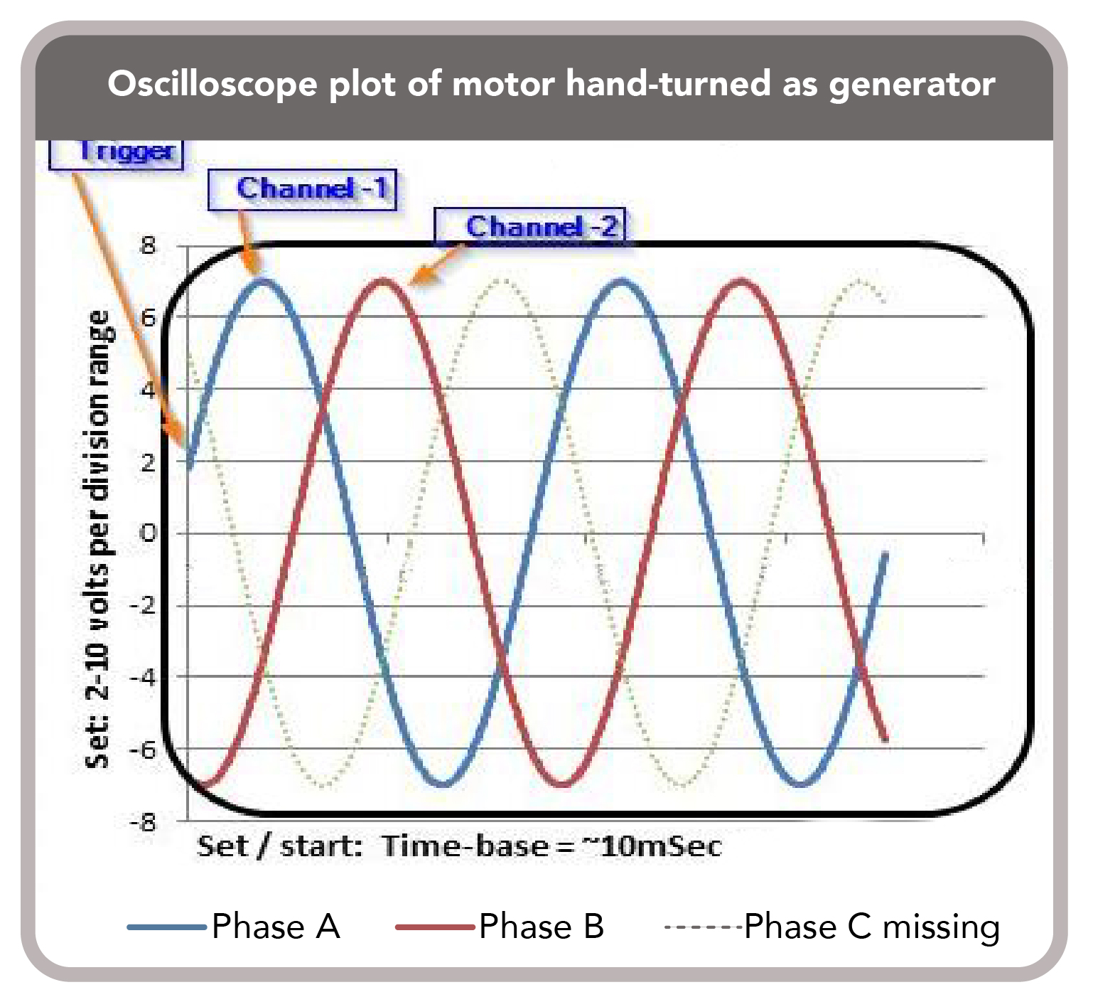
9. If your present Bemf waveforms look like Channel 1 and 2 (blue leading red respective to the trigger in the figure titled, Oscilloscope plot of motor hand-turned as generator) label the wire going to Channel 2 as phase C, and the wire connected to the oscilloscope ground clips as Phase B. If your Channel 2 waveform looks like it is shifted to the right over the dotted green line shown in the figure, label the wire going to Channel 2 as phase B … and the wire connected to the oscilloscope ground clips as phase C.
Poka yoke: Double-checking motor wiring
For the ninth step above (for using an oscilloscope to observe motor waveforms) switch the wires between the oscilloscope ground clips and Channel 2 and verify the waveforms now look like Channel 1 and Channel 2 as noted. if not, you have made a mistake somewhere along the line. Here, do make sure you’re rotating the rotor in the correct direction and that Channel 2 has been Inverted.
Once output appears as expected, your motor phases can be successfully identified and labeled A, B, and C by outlining how node voltages relate to each other — VAB, VBC, VCA, VAB, VBC, and so on from the motor’s Bemf as the servo motor’s rotor is rotated in its defined direction. In our example, this is clockwise when looking into the rear endbell. Note that the node VAB or VAB should be read as the voltage at node A with respect to node B.
Then each node is labeled for future reference with only one specifically identified letter. Again, there is good reason for this.
Hurley Gill is senior applications and systems engineer at Kollmorgen in Radford, Va. He’s a 1978 Engineering Graduate of Virginia Tech who has been engaged in the motion control industry since 1980. He can be reached at hurley.gill@kollmorgen.com.
Kollmorgen was founded in 1916. Today, its knowledge of motion systems and components, industry-leading quality, and deep expertise in linking and integrating standard and custom products continually delivers breakthrough motion solutions that are unmatched in performance, reliability, and ease-of-use. This gives machine builders around the world an irrefutable marketplace advantage and provides their customers with ultimate peace-of-mind. For more information, visit www.kollmorgen.com.







Leave a Reply
You must be logged in to post a comment.