Servomotor and stepper motor technologies are indispensable in today’s mechatronic machine designs. However, clear understanding of the advantages and disadvantages of both make it easier to identify which is best for a given application.
By Hurley Gill • Senior Systems and Application Engineer| Kollmorgen
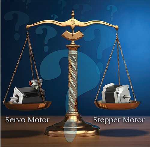
If a given motion task can be done with either a stepper or servomotor-based design, the application’s exact needs (present and future) for repeatability, accuracy and flexibility dictate which is most suitable. Other factors that can help engineers pick between the two include environment, life expectancy, operating noise and energy use. However, when a machine axis allows use of either technology, engineers must use specific knowledge of the machine function and foresight to pick.
The ultimate motion-design goal is to get target performance from a given machine while balancing capabilities and cost. Picking a servomotor or stepper motor for a given application affects the odds of a successful motion design, so machine builders must consider the technical advantages and disadvantages of both.
Machine designers shouldn’t limit use of steppers or servos based on personal preference or comfort level, but learn where each technology works best for actuating specific mechanisms. Today’s digital stepper-motor drives enhance flexibility, drive features and communication protocols with integrated circuits and simplified programming. The same is true of servomotor systems. Here, higher torque density as well as improved electronics, algorithms, and higher feedback resolution have also boosted system bandwidth capabilities, with lower initial and overall operating costs for many applications.
Where stepper motors do and don’t outperform servomotors
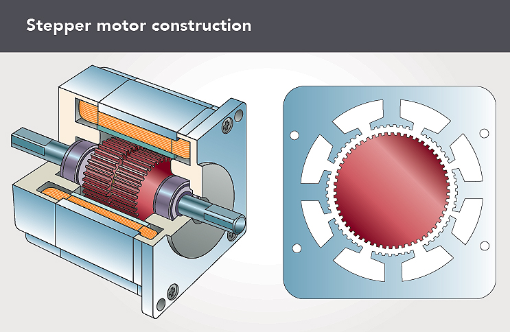
Stepper motors have several major advantages over servo systems. They are typically lower cost, have common NEMA mountings, offer lower torque options and require less costly cabling. In addition, their open-loop motion control component simplifies integration and use for machine builders and end users.
• Consider torque and speed. Steppers are typically sized for twice their continuous requirements to handle acceleration/deceleration torque—or for peak-torque requirements. In contrast, designers typically size servomotors to specific application velocities and torques for maximum intermittent acceleration or deceleration, holding torque (if applicable), and continuous RMS requirements over the complete motion profile.
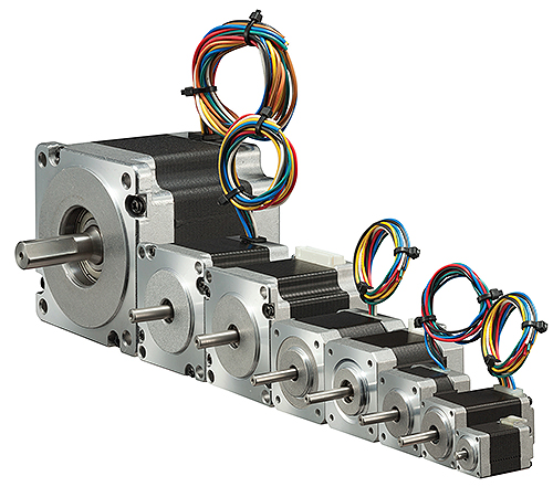
In general, if an application requires high throughput, speed and bandwidth for disturbance correction, or high rpm with or without tight coordination between axes, servomotors are the best option. If point-to-point position performance or rpm requirements are modest (as a function of the process loads or expected disturbances), steppers may be a better choice. Additionally, when loads are within reason, a stepper’s ability to hold position (with holding torque under power and detent torque under no power) can be an advantage.
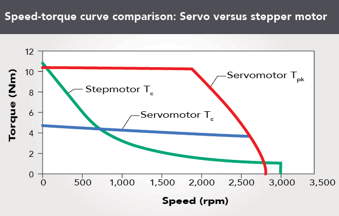
Speed-torque curves highlight the difference between stepper and ac permanent-magnet (PM) servomotors of equal volume. Steppers typically generate higher continuous torque at lower speeds than servomotors. However, servomotors produce intermittent peak torques in this same low-speed range and produce peak and continuous torques over a much wider (and higher) speed range.
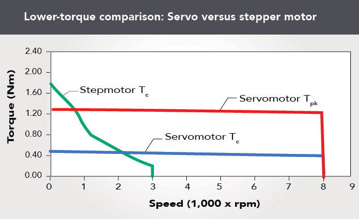
• Consider some specific examples. Video inspection axes and automated machine axes for adjustment and setup often use steppers. That’s because these axes are easier to design into control systems and less expensive to setup. Plus, when such axes lock into a position, steppers can turn off (with an on/off function) to boost efficiency. Properly installed steppers are less prone to failure than servos because of their simplistic open-loop control, which only needs winding-to-drive matchup (This is in contrast to the motor-drive-to-mechanism tuning with feedback circuits required by closed-loop systems).
• Today’s stepper drives offer distinct advantages. Newer design techniques have improved stepper-motor performance with built-in feedback; end-of-move damping (for reduced settling times while maximizing accuracy); soft starting (so there’s no quick motion or jerk on power-up); and anti-resonance modes—for optimizing torque, stability and noise reduction (audible or otherwise).
Other stepper drive capabilities include idle current reduction (or IRC for reduced motor heating during standstill) and easily controlled operation modes between full stepping, half stepping and microstepping.
Although most properly sized steppers are extremely accurate running open loop in the selected step mode, built-in feedback provides additional precision without the cost of an external feedback device. Microstepping techniques also smooth torque and motion at low speeds and boost resolution at high speeds (with smaller step sizes than full-step or half-step setups).
• Modern stepper motors also offer more capabilities than in the past. They now come in higher power ratings than earlier-generation steppers. Advances in design have led to smaller airgaps, larger and stronger magnets, and rotor oversizing. Increasing the rotor’s diameter generates more torque per unit volume. Here, physical frame size and stepper motor winding stays the same while the rotor’s diameter and inertia are bigger. Of course, the larger rotor inertia can affect acceleration and deceleration times for a given application. Even so, such motors let more applications use a given stepper frame size thanks to a lower inertia ratio of load (J_load) to rotor (Jm). Generally, stepper motor systems are sized with a J_load:Jm of less than 30:1, but with slower accelerations and decelerations and advanced microstepping techniques, inertia ratios of 200:1 are possible.
• One last item to mention here. Today’s modern stepper drives handle stall detection electronically, so optional feedback devices, when used, help with position correction due to component misalignment, noise and lost pulse (position) information. A stepper motor with feedback, depending on the stepper drive, has less velocity ripple and uses less power than open-loop equivalents … and higher residual torque at low speeds than an equivalent three-phase servomotor.
So designers must be discerning in regard to the work an axis does, because stepper motor applications requiring feedback can approach the cost of a servo system, and what may be an operational advantage in one application may be a disadvantage in another. Closed-loop stepper systems don’t typically outperform lower-priced servomotor systems, so designers should carefully consider their benefits and drawbacks for the application at hand.
Where servomotors do and don’t outperform stepper motors
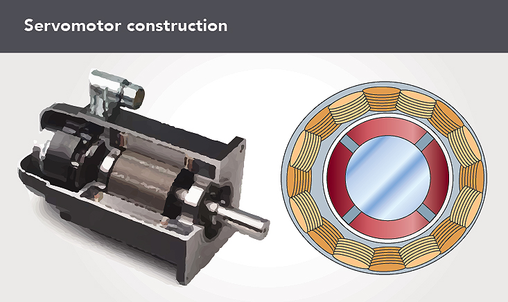
Servomotors have several advantages over steppers. They can develop a high torque output over a wide speed range on demand, and are available in wider torque ranges and higher voltages (up to 480 Vac). They respond to disturbances with torque far exceeding their continuous capability and use only the power needed to move an axis to the commanded motion. In addition, servomotors are compact.
• Servodrives offer advantages as well. Motor-drive compensation, or tuning, once considered the bane of servo use is now mostly history. Today, the newest digital servodrives have software and hardware capabilities for better user experience and remarkable compensation flexibility. In fact, some servo systems autotune themselves after automatically configuring the motor, drive and feedback. Servodrives that autotune adapt to the given motor-drive-mechanism setup while maintaining performance without the need of any manual control-loop fine tuning.
• Reconsider torque and speed. Although servomotors run at high speeds, they can accurately run at extremely low speeds under precise control, even down to 1 rpm and below with proper preparation. Steppers are accurate and usually more economical for low-speed applications that run at less than 1,000 rpm. However, above 1,000 rpm, stepper-motor torque begins to fall off due to core losses and magnetic circuit time constants.
In contrast, servomotors with comparable torque don’t start falling off until around 2,000 to 4,000 rpm or more. Direct-drive servo applications powering high-inertia loads typically run at less than 1,000 rpm, while typical servo applications with a mechanically advantaged drivetrain run at any number of speeds within the working capability envelope.
If a given application needs a speed range between 1,000 to 3,000 rpm, the most suitable motor technology depends on requirements such as peak torque at speed, continuous (RMS) torque and speed, and repeatability.
At stall (low speeds less than 50 steps/sec or 15 rpm) or when holding a load with no movement, stepper motors—especially with oversized rotors—can produce more torque than servos for a given frame size (though newer servomotor designs are encroaching on this capability). All that torque lets steppers produce extremely accurate and stiff low-speed motion without a gearbox or other mechanical advantage.
In contrast, direct-drive servomotors with higher pole count and high-resolution feedback often drive industrial process applications requiring typical velocities of less than 1,000 rpm without a mechanical advantage such as a gearhead.
When a stepper motor is at rest, it uses continuous energy and there’s absolutely no movement (unless overloaded). When unpowered, for some applications a stepper motor’s detent torque can hold position.
In contrast, a servomotor is never at rest when on, due to constant closed-loop error correction — at which time it only uses the energy required to maintain its commanded position. Constantly varying position-loop error causes the servo’s output shaft to move back-and-forth (though on a scale that may be unnoticeable) while it continuously looks for minimum error. This continuous back-and-forth actuator motion is called hunting.
A similar movement is dither —a purposely induced actuator movement, as in a valve to continuously overcome the issues of stiction. Hunting is unnoticeable in most applications involving only a few feedback counts (relative to the percent of total resolution), but can be unacceptable in others (though higher-resolution feedback devices reduce the typical hunting delta).
Where repeatability and resolution are issues, servomotors are the traditional choice. However, steppers are making inroads in these applications wherever the load is predictable or subject to only small external forces and disturbances, and where tight coordination between axes is unnecessary. Here, steppers running open loop can save 20 to 30% on initial machine expense over comparable servo solutions.
• Regarding torque, designers should select the motor that provides higher values at the application’s speeds. Engineers can determine which motor excels by comparing speed-torque curves. For a given price, most designers prefer servomotors. For constant or variable loads, servo systems recover from overload conditions where stepper systems cannot. Steppers output a lot of torque from a small package for speeds less than 1,000 rpm. In contrast, servos can handle torque requirements below and well above 1,000 rpm.
• Determining a system’s load inertia and inertia matching can help engineers pick between motor types. As a rule of thumb, steppers usually don’t exceed a 30:1 ratio of load inertia to motor inertia (J_load:Jm). In contrast, direct-drive servo systems with no compliance (except the driven steel) and high-resolution feedback can run 200 to 300:1 (J_load:Jm ratio) and higher—with quick response times relative to legacy feedback technologies.
In the past, traditional servomotor setups (with mechanical advantage through power-transmission components) needed a J_load:Jm ratio in the range of 1:1 to 5:1 (which later became 1:1 to 8-10:1) to get quick response times and high acceleration or deceleration.
Today, a system that has the highest available feedback resolution and minimal compliance and/or backlash is capable of 1 to 15:1 and higher inertia ratios for many applications. These deliver the best operational efficiency with little additional risk. Higher inertia ratios are application dependent, not only relative to the target machine specification, but also in relation to the mechanism’s compliance and backlash. For direct-drive systems, required stiffness often demands larger shafts and bearings, and even the compliance of the machine fixture and motor stand comes into play.
Other parameters to help engineers decide between servomotors and stepper motors
The next application factor to help engineers pick between servomotors and stepper motors is the need for coordination of axes. Applications that need axis coordination should use servo-controlled systems to leverage their tight synchronization capability (high bandwidth and high resolution allow for fast correction of signal disturbances and command changes). Properly sized open-loop stepper motor systems stay in sync without confirmation feedback, but are limited to point-to-point moves with only sequential or pseudo-coordination between axes possible.
• Next consider cabling and motor-drive adjustments. One recent change improving servo reliability (and minimizing maintenance) is the reduction in the number of power and feedback wires the average servomotor needs.
Manufacturers have also taken guesswork out of closed-loop system servo tuning (motor-drive-mechanism compensation) and determining when a system needs maintenance. Automated or calculated tuning techniques and built-in diagnostic programs help simplify these tasks for the user. In addition, most servodrives can use traditional Step and Direction inputs that have been used to interface with steppers for years. Servos using this capability are typically in a position mode that eliminates the potential loss or addition of commanded motor steps.
In fact, this is a good segue to discuss one of the most common issues with stepper motor systems when run on the edge of their capability — the loss or addition of motion steps relative to the number of commanded steps. The problem is most apparent during acceleration or deceleration.
Step losses typically result from overly large inertia (affecting acceleration) or higher-than-desirable friction. In contrast, the addition of steps typically results from noise or too large inertia (affecting deceleration). Due to the accumulation of extraneous (+) and lost (-) motion steps, it can take hours before some manufacturing tolerance is exceeded. Nonetheless, stepper motors are still simpler because they have fewer wires to connect with minimal amounts of motor-drive adjustment to get a system up and running.
• Accuracy and resolution are other parameters to help pick an axis design’s motor type. Note that theoretical and actual resolution differ for stepper systems. For example, a two-phase, full stepping, 1.8° step-angle motor may have 200 possible positions in one revolution (from 360°/1.8°), but whether the motor achieves that depends on how the motor was sized for the application. The same is true of half-stepping and microstepping motor-drive modes. A 1.8° microstepper specified as having 10 microsteps per each full step won’t necessarily find any position within 0.18°.
Additionally, several commanded microsteps can transpire before there’s enough torque buildup to overcome friction and load inertia to get moving. In a real-world situation, the motor could easily jump one or more microsteps beyond the number commanded and stabilize there. When positioning-resolution requirements must exceed 200 steps/rev, steppers can use a feedback encoder to get 1,000 steps/rev or better. Five-phase motors and (in some cases) microstepping motors can also improve the steps per revolution.
Servomotor resolution is theoretically infinite, but in closed-loop operation, system positioning depends primarily on the resolution of the feedback device, be it a sine encoder, resolver or a digital (TTL) type encoder. Today’s high resolution feedback devices can approach between 221 (2,097,152) to 228 (268,435,456) counts per motor revolution, plus optional multi-turn capability to 4,096 turns. Multi-turn feedback capable devices are available for an axis’ absolute position on machine power-up, eliminating the initial axis power-up homing cycle.
• Repeatability is yet another parameter that differentiates servomotors and stepper motors. Servomotors are extremely repeatable because they run closed loop. But steppers can be just as repeatable in many applications, especially when running in one direction. That said, when an ICR mode is used or the load increases (like during a direction reversal) and exceeds the stepper’s capabilities, the situation changes. Similar to how a gearbox must take up backlash, the stepper must catch up to system command. During the first move in a new direction, motor accuracy is affected because the stepper is overcoming inertia and friction (effects of the load). Once that happens, the system regains its specified repeatability, but it may have lost or gained actual position steps over those commanded.
• Consider input power as well. A stepper motor is equivalent to an inductor in series with a resistance. So, the current that produces torque needs time to rise. This time limits the speed at any given voltage, so increasing motor speed in a given application may require higher voltages.
Servo system requirements are similar, but (within its capability envelope) the drive’s control loops supply required voltage and current to the servomotor to meet the load’s demand relative to the move command and feedback error. When a servomotor system is forced to work (for whatever reason) outside its operational envelope, even for a millisecond, it’s no longer under control and doesn’t operate as a servo. Reprint info >>
Kollmorgen | www.kollmorgen.com





Leave a Reply
You must be logged in to post a comment.