• Skip to primary navigation
  • Skip to main content
  • Skip to primary sidebar
  • Skip to footer
  • Advertise
  • Subscribe

Motion Control Tips

Automation • Motion Control • Power Transmission

  • News
    • Industry News
    • Editor Blogs
  • Controls
    • HMIs
    • PC-Based Controllers
    • PLCs + PACs
    • Stand-Alone Controllers
    • Software
  • Drives
    • Servo Drives
    • Stepper Drives
  • Encoders
    • Absolute Encoders
    • Incremental Encoders
    • Rotary Encoders
  • Mechanical
    • Bearings
    • Brakes + Clutches
    • Belt + chain
    • Couplings
    • Gears + Gearing
    • Lubrication
    • Shock + Vibration Mitigation
    • Springs + Rings + Seals
  • Linear
    • Actuators
    • Linear Motors
    • Linear Encoders
  • Motors
    • AC Motors
    • DC Motors
    • Brushless Motors
    • Gearmotors
    • Piezo Motors
    • Servo Motors
    • Stepper Motors
  • Systems
    • Conveyors + linear transport systems
    • Gantries + Stages
    • Rotary Tables
    • Grippers + End Effectors
    • Robotics
  • Networks
    • Connections + Sliprings
    • Fieldbuses
    • I/O
    • Sensors + Vision
  • Resources
    • FAQs
      • Motion Casebook
      • Motion Selection Guides
    • Suppliers
    • Video
You are here: Home / FAQs + basics / How are complementary signals used to mitigate encoder noise?

How are complementary signals used to mitigate encoder noise?

July 23, 2017 By Danielle Collins Leave a Comment

encoder noise
Electrical noise in encoder signals can cause the receiver to make false counts.
Image credit: Encoder Products Company

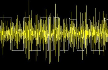
Electrical noise is a common problem that occurs during the transmission of an incremental encoder’s signal to the receiving electronics, especially when the cable lengths are very long. Stray electromagnetic fields or currents induce unwanted voltages into the signal. These voltages can cause the receiver to make false counts, producing errors in the position or velocity feedback.

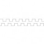
The primary way to alleviate electrical encoder noise is to use TTL output – also known as differential line driver output. This output format provides not only the standard A and B square wave signals and a Z reference signal, it also includes their complementary signals, /A, /B, /Z (sometimes written as A’, B’, and Z’). These complementary signals are produced by splitting the output of each channel (A, B, and Z) into two signals that are 180 degrees out of phase (complements) with each other. In other words, when the A signal is high (logic state 1) the A’ signal will be low (logic state 0). The receiving electronics take the state of that channel as the difference between the two signals

In order for the complementary signals to be read, however, the receiving electronics must have a circuit that is designed for differential input – known as line receiver input. In addition, the wires for each channel (A and A’, for example) should be a twisted pair. In this twisted pair of wires, any electrical encoder noise that is induced will be the same on each signal. The receiving electronics recognize only the difference between the two signals, and because the signals are complements (equal in magnitude, with 180 degree phase lag) but the noise is common mode (equal on each signal, with no phase lag), the noise is cancelled out on the receiving end.

encoder noise
With complementary signals, noise is cancelled out on the receiving end.
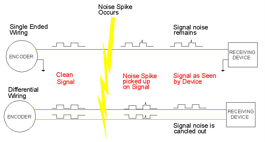
Image credit: Quantum Devices Inc.

Q: What is differential line driver output?

 A: Line driver is an output method that uses an integrated circuit designed for data transmission at high speeds over long distances and complies with the RS-422 standard. The term “differential” refers to the fact that this output method uses two complementary signals on each channel.


You Might Also Like

Filed Under: FAQs + basics, Featured, Incremental Encoders

Reader Interactions

Leave a Reply

You must be logged in to post a comment.

Primary Sidebar

LEARNING CENTER

Design World Learning Center

Motion Control Handbook

“mct
EXPAND YOUR KNOWLEDGE AND STAY CONNECTED
Get the latest info on technologies, tools and strategies for Design Engineering Professionals.

RSS Featured White Papers

  • Robotic Automation is Indispensable for the Logistics Industry’s Continued Growth and Success
  • Reliable Linear Motion For Packaging Machines
  • Polymers Outperform Metals In Precision Gearing

Footer

Motion Control Tips

DESIGN WORLD NETWORK

Design World Online
The Robot Report
Coupling Tips
Linear Motion Tips
Bearing Tips
Fastener Engineering.
Wire and Cable Tips

MOTION CONTROL TIPS

Subscribe to our newsletter
Advertise with us
Contact us
About us

Copyright © 2025 · WTWH Media LLC and its licensors. All rights reserved.
The material on this site may not be reproduced, distributed, transmitted, cached or otherwise used, except with the prior written permission of WTWH Media.

Privacy Policy | RSS