
One way to classify gears is by the profile of the gear teeth: involute, cycloidal, or trochoidal. (Note that trochoidal gears are used primarily in pumps.) The majority of gears used in motion control applications — including spur, helical, and bevel designs — are involute gears. However, cycloidal gears are a good choice for motion control applications that require very high gear ratios (often greater than 100:1), low friction, and excellent wear resistance.
The tooth profile of an involute gear is the involute of circle, which is the curve that would be traced by a point on a line that rolls on the circumference of a circle. Another way to visualize the involute of a circle is to imagine the curve that the end of a string wrapped around a cylinder would make as the string is unwrapped from the cylinder.
In contrast, the tooth profiles of cycloidal gears are based on cycloids. To understand cycloidal gears, it’s important to understand epicycloids and hypocycloids.
An epicycloid is the curve created when a circle rolls on the outside of another circle (referred to as the “base circle”).
Image credit: Wolfram MathWorld
A hypocycloid is the curve created when a circle rolls on the inside of a base circle.
Image credit: Wolfram MathWorld
In a cycloidal gear, the part of the tooth flank that lies outside the pitch circle (known as the addendum) is epicycloidal. Conversely, the part of the tooth flank that lies inside the pitch circle (known as the dedendum) is hypocycloidal.
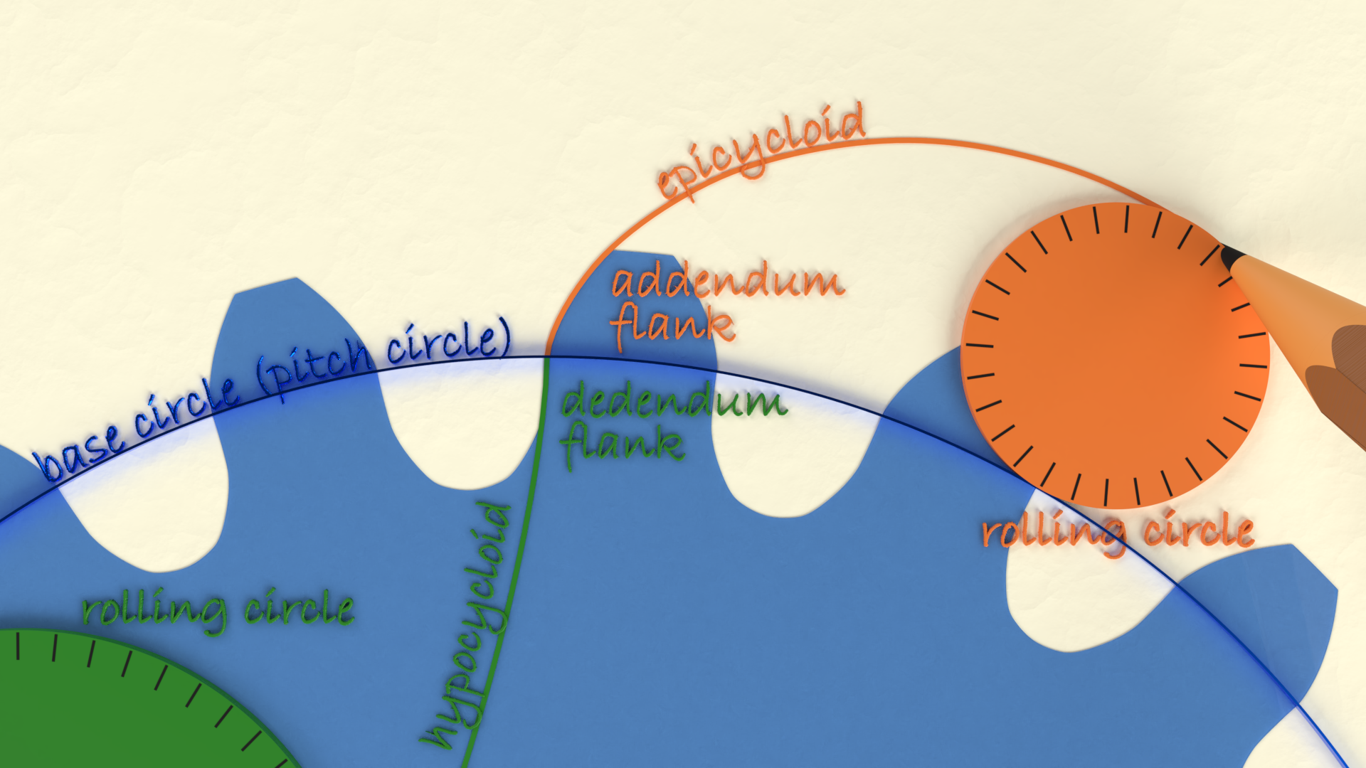
Image credit: Tec-science
A unique principle of cycloidal gears is that the outer rolling circle used to create the addenda tooth flanks (epicycloids) on one gear is used as the inner rolling circle to create dedenda tooth flanks (hypocycloids) of the other gear. This ensures a constant angular velocity and holds up the fundamental law of gearing, which states that the ratio of the gears’ angular velocities must remain constant throughout the meshing of the gears.
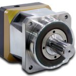
A cycloidal gearbox uses the principles of cycloidal gears to provide high gear ratios (often 100:1 or greater) with excellent torsional stiffness, good shock load capacity, stable backlash over the gearbox life, and low wear.
There are various designs of cycloidal gearboxes, but the basic principle consists of an input shaft that is eccentrically mounted to a drive member or bearing, which drives a cycloidal disc in an eccentric motion. As the disc rotates, the lobes of the cycloidal disc act like teeth and engage with pins on a stationary ring gear. The cycloidal disc also has roller pins that protrude through the disc, and these pins attach to an output disc which transfers motion to an output shaft.
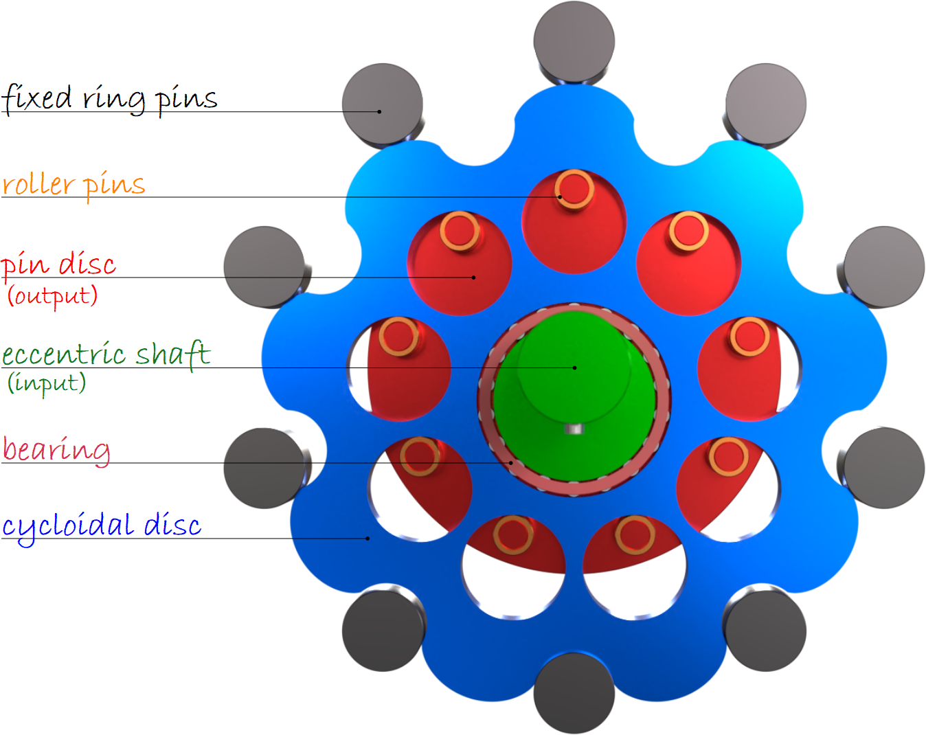
The number of lobes (teeth) on the cycloidal disc is lower than the number of pins (teeth) on the ring gear, which provides speed reduction and torque multiplication. To prevent “wobbling” of the output shaft, the roller pins connected to the output disc are mounted in holes slightly larger than the pin diameter. A single cycloidal disc experiences unbalanced forces, which can be compensated by using a second cycloidal disc, offset from the first by 180 degrees.
Cycloidal gears are much more difficult to manufacture than involute gears, requiring extremely accurate manufacturing and assembly. But they do offer significant benefits in some applications. First, they can provide transmission ratios up to 300:1 in a relatively small package — especially concerning the length of the gearbox — since they don’t require “stacking” of gear stages as planetary designs do.
Cycloidal gears also experience lower friction and less wear on the tooth flanks due to their rolling contact and lower Hertzian contact stress. And their good torsional stiffness and capacity to withstand shock loads make them ideal for heavy industrial applications that also require servo precision and stiffness.
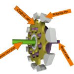 Feature image credit: Onvio

Leave a Reply
You must be logged in to post a comment.