
Updated May 2016. || Application-tailored and custom gearboxes are increasingly common, mainly because they’re easier than ever to manufacture to specification.
That’s not to say that the design work isn’t challenging. However, modern manufacturing lets some suppliers make gearboxes and components to meet specific application requirements.
New supplier approaches to giving engineering support as well as new machine tools, automation and design software now let OEMs and end users get reasonably priced gearing even in modest volumes.
When enlisting help from a consultant or manufacturer, an engineer is more likely to get gearing that mounts properly and performs to specification after reviewing the following and answering as many of these questions as possible:
• What’s the input speed and horsepower?
• What’s the gearbox target output speed or output torque? This partially defines the required gear ratio.
• What are the characteristics of use? How many hours per day will the gearbox run? Will it need to withstand shock and vibration?
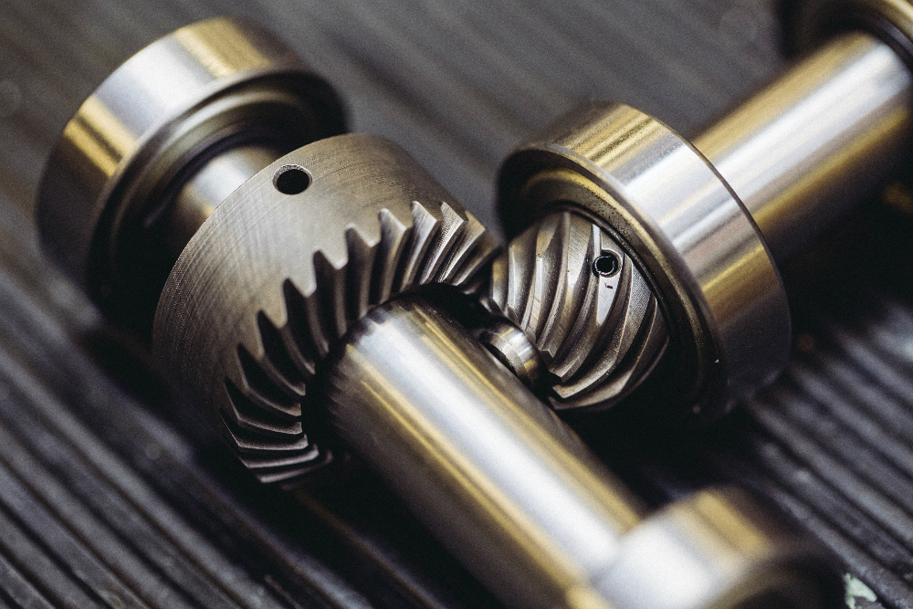
• How overhung is the load? Is there internal overhung load? Remember that bevel gears usually can’t accommodate multiple supports, as their shafts intersect … so one or more gears often overhang. This load can deflect the shaft which misaligns the gears, in turn degrading tooth contact and life. One potential fix here is straddle bearings on each side of the gear.
• Does the machine need a shaft or hollow-bore input … or a shaft or hollow-bore output?
• How will the gearing be oriented? For instance, if specifying a right-angle worm gearbox, does the machine need the worm over or under the wheel? Will the shafts protrude from the machine horizontally or vertically?
• Does the environment necessitate corrosion-resistant paints or stainless-steel housing and shafts?
Related article: What the different gear variations and applications? Technical Summary
Service factor: The starting point for most gearbox manufacturers is to define a service factor. This adjusts for such concerns as type of input, hours of use per day, and any shock or vibration associated with the application. An application with an irregular shock (a grinding application, for example) needs a higher service factor than one that’s uniformly loaded. Likewise, a gearbox that runs intermittently needs a lower factor than one used 24 hours a day.
Class of service: Once the engineer determines the service factor, the next step is to define a class of service. A gearbox paired to a plain ac motor driving an evenly loaded, constant-speed conveyor 20 hours per day may have a service class 2, for example.
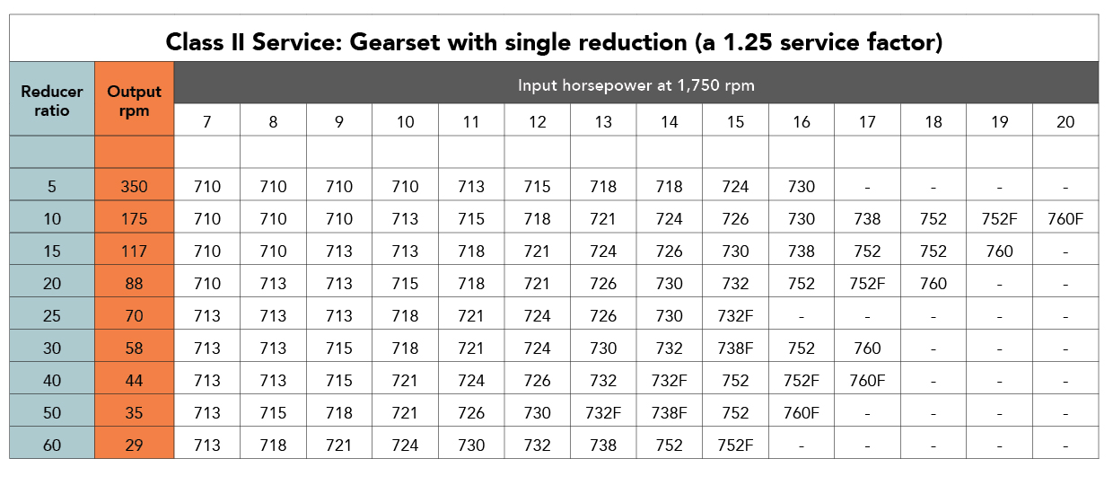
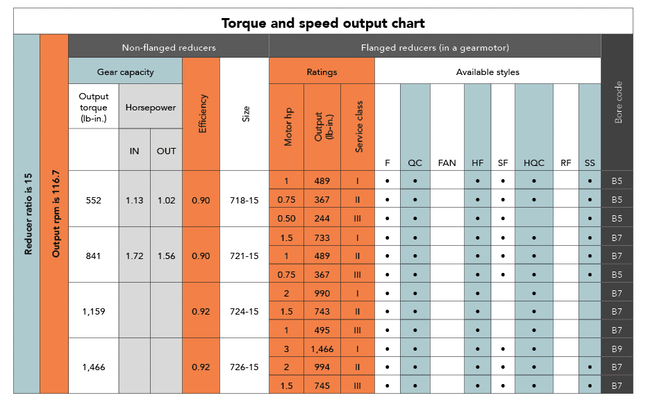
This information comes from charts from gearbox manufacturers that list classes of service. To use these charts, the design engineer must know input horsepower, application type and target ratio. For instance, suppose that an application needs a 2-hp motor with a 15:1 ratio. To use the chart, find the point where 2 hp and 15:1 ratio intersect. In this case, that indicates a size 726 gearbox. According to one manufacturer’s product-number system, size 726 defines a gearbox that has a 2.62 center distance. Such charts also work in reverse, to let engineers confirm the torque or speed of a given gearbox size.
Overhung load: After the designer picks a size, the gearbox manufacturer’s catalog or website lists values for the maximum overhung load that is permissible for that sized unit. Tip: If the load in an application exceeds the allowed value, increase the gearbox size to withstand the overhung load.
Mounting: At this point, the designer or manufacturer has defined the gearbox size and capability. So, the next step is to pick the mounting. Common mounting configurations abound, and gearbox manufacturers offer myriad options for each unit size. A flanged input with hollow bore for a C-frame motor combined with an output shaft projecting to the left may be the most common mounting, but there are many other choices. Options such as mounting feet for either above or below the body of the gearbox, hollow outputs, and input and output configuration are all possible. All gearbox manufacturers list their mounting options as well as dimensional information in catalogs and websites.
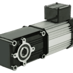
Lubricant, seals and motor integration: Once unit size and configuration is complete, a few specifications remain. Most manufacturers can ship gearboxes filled with lubrication. However, most default to shipping units empty to let users fill them on site. For applications where there is a vertical shaft down, some manufacturers recommend a second set of seals. Finally, because many gearboxes eventually mount to a C-frame motor, many manufacturers also offer to integrate a motor onto the gearbox and ship the assembly as a single unit.
It’s best to work with consultants and even use custom gear designs if the application needs a unique motor-gearbox combination. Some combinations are more efficient. In fact, working with manufacturers to get a pre-engineered geamotor ensures that the motor-gearbox combination will work and deliver the specifications from calculations and testing performed by the manufacturer. Review the manufacturer’s performance calculations to determine if the chosen gearmotor will cause any issues within the application.
Remember that today’s custom and standard gearing aren’t mutually exclusive. Where fully-custom gearboxes aren’t feasible (if quantities aren’t high enough, for example) consider working with manufacturers that sell gearboxes built to order from standard modular subcomponents. Otherwise, for small quantities of true custom gearboxes, look for manufacturers that leverage the latest CAD software, CAM software and machine tools to streamline post-processing work and reduce the cost of one-offs.
One final tip: Once the gearmotor has been chosen and installed in the application, perform several test runs in sample environments that replicate typical operating scenarios. If the design exhibits unusually high heat, noise or stress, repeat the gear-selection process or contact the manufacturer.
More about gears for power transmission and speed reduction
Top gear trend for this decade: Varied designs faster
What are gears and their different variations and applications? Technical Summary
Gearmotors FAQ: When to pick a pre-engineered gearmotor and when to go it alone?
Gearmotors FAQ: What is the Dept. of Energy’s new Small Motor Rule?
Gearmotors FAQ: What are efficiency requirements for continuous vs. intermittent duty gearmotors?
Leave a Reply
You must be logged in to post a comment.