by Dan Jones, Incremotion Associates
New fan designs help reduce heat, dust and excessive moisture in cooling applications.
An important but often secondary consideration in control systems and control cabinets is cooling. Electronic control equipment such as controllers and drives, especially equipment that’s confined to enclosures with little or no natural air movement, is especially susceptible to excessive heat. Electronic equipment often generates a lot of heat that must be dissipated and removed, otherwise it can negatively affect equipment, shortening useful life and causing malfunctions.
To operate normally, electronic control equipment needs to maintain a safe operating temperature inside the equipment box or enclosure. Adding a range of environmental conditions involving heat (both internal and external), dust and excessive moisture (water) complicates the design of any control panel. However, new cooling modules are helping to solve these challenges.
Cooling a control panel
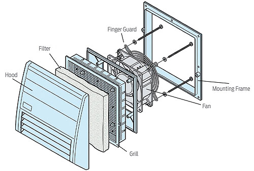
A typical fan installation contains a finger-protected guard for user safety. However, while the finger guard protects the user, it’s not effective against dust and water invading the control box and panel. One must be concerned with deteriorating performance. In an extreme case, the electronic control equipment may be disabled.
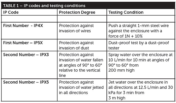
Newer cooling modules can be equipped with one or more filter units capable of preventing dust and water from entering the control equipment. These cooling modules are built to meet exacting requirements. For instance, The International Electro-technical Commission (IEC) standard IEC 60529 offers different levels or degrees of protection levels (IPs) against bodily intrusion (fingers), dust and moisture (condensation and water flow). Table 1 contains the IP code designations, letter marking designations and testing conditions. The first IP digit indicates the object size protected against, and the second digit indicates the level of protection that the enclosure provides against harmful entry of any form of water.
Filtering various objects
Filters are the most effective method of blocking large objects and dust particles as small as 0.03 µm. Most filters are rated by their capability or efficiency in removing dust particles (IPEX) from air that passes through them. One thing to keep in mind is that as the filtering operation continues the filter’s collection capability is lowered, meaning that the filters require periodic cleaning.
In the configuration known as the flat plate type, two side-by-side axial fans provide air flow to cool the electronic control panels in both discharge and suction airflow configurations. A guard protects fingers from interfering with the moving fan blades and all cooling parts are screwed together to form the flat plate-cooling module.
A plastic or metal hood prevents water from entering the inside of the module. It also provides a ventilation clearance for the module body and the nearby wall. A grill holds the filter medium and secures the module body to the mounting frame. A single axial fan is used to create the needed axial airflow. The filter medium removes the dust and water drops from the air taken into the electrical control cabinet.
Computing the needed airflow
Selecting the optimum cooling performance involves choosing the fan airflow under the desired environmental conditions. Selecting the correct axial fan involves a number of calculations. The required airflow calculations use a graph designated as the Quick Air Flow Estimation Graph. This figure is a composite of two separate charts properly aligned vertically to provide a viable solution.
This process begins with the equation listed below:
V = 1/20 x {(Q/ΔT-U) x S} x SF
where:
Q = heat factor in watts
ΔT = selected temperature rise in degrees C
U = heat transfer co-efficient in watts/(sq meter x Kelvin)
S = effective heat radiating area in square meters
SF = safety factor
V = computed air flow in cubic meters per minute
The calculation process begins below:
First, select Q = 450 W and ΔT as 20° C temperature. Locate the intersection of these two elements located on the Quick Air Flow Estimation graph and label this intersection as point A. Next, draw a horizontal line to the right intersecting the family of skewed lines at the correct value of the effective Heat Radiating Area or cross section. The intersection of these two performance parameters is labeled as point B.
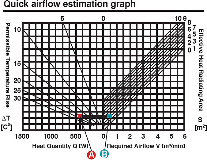
Then construct a vertical line downward from point B to intersect the X axis. The X-axis value on the right side indicates the airflow value which is 0.5 m3/min. Multiply this value by a safety factor of 2 to achieve the final answer of 1.0 m3/min or 35.3 ft3/min.
Identifying the control equipment operating environment
There are a number of items to evaluate when selecting a fan to provide sufficient air flow to cool the inside of a control box. The most important are:
• the needed air flow
• the degree of pollution or contamination
• the air clearances and creepage within the control box
• whether there more accumulated contaminated dust and other small particles outside or inside the control box
A clean room application provides a good working example. In this environment, the pollution degree is designated as pollution degree 1. An axial fan is used with a filter panel in a discharge type configuration. The filter works to keep the dust inside the control panel from entering the outside environment.
The fan and filter panel of the selected axial fan should provide sufficient cooling to effectively cool the control panel box. And proper cooling of the control panel electronics significantly expands the control box operating life.
Going forward, one can expect the cooling requirements for control panels to become more challenging. More diversified solutions are needed in combination with simpler mounting configurations and user-friendly installations.
Oriental Motor USA
www.orientalmotor.com


Leave a Reply
You must be logged in to post a comment.